DCA-15SPX3 specifications
The Multiquip DCA-15SPX3 is a versatile and robust generator designed for a range of applications, making it an ideal choice for contractors, events, and emergency power needs. With a powerful output of 15 kW, this generator is equipped to handle a variety of electrical loads, providing reliable, consistent power.One of the standout features of the DCA-15SPX3 is its impressive fuel efficiency, thanks to a quiet-running and high-performance engine. This model is designed with a durable, weather-resistant enclosure that not only protects the generator from harsh environmental conditions but also reduces noise levels, making it suitable for use in residential areas or during events where noise control is essential.
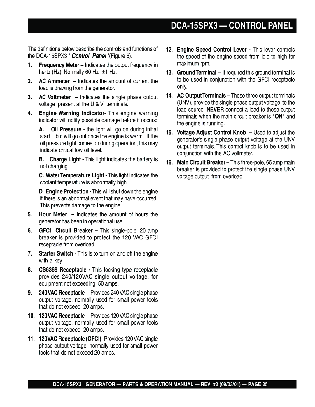
The generator operates on diesel fuel, which is known for its efficiency and longevity compared to gasoline-powered counterparts. The DCA-15SPX3 has a user-friendly control panel, offering easy accessibility to start and stop operations. Additionally, it includes built-in safety features, such as low oil shutdown and overload protection, ensuring that the generator operates safely and efficiently.
The DCA-15SPX3 also incorporates advanced technology like digital automatic voltage regulation (AVR), which provides stable voltage output and reduces the likelihood of damage to sensitive electronics and equipment. This technology ensures that the generator maintains a consistent power supply even as the load varies, enhancing its suitability for both light commercial and heavy industrial applications.
With a compact design, the generator is easy to transport and set up, making it convenient for on-the-go power solutions. It features built-in lifting hooks and is mounted on a robust chassis for better mobility. The unit’s low maintenance requirements further enhance its appeal, allowing users to focus more on their tasks rather than routine upkeep.
Overall, the Multiquip DCA-15SPX3 stands out in the market for its balance of power, efficiency, and ease of use, making it an invaluable asset for professionals requiring dependable power in diverse settings. Whether used for temporary job sites, special events, or as a backup power source, it delivers the performance and reliability expected from a high-quality generator.

