DCA-25SSI — OUTPUT AMPERAGE SETUP
Receptacle Use
When the UVWO terminals are providing power, the receptacle power available decrease. Do not exceed receptacle power available listed on Table 8.
Table 6. Receptacle Use
|
| Receptacle |
|
| Power |
Power in Use | Available | |
|
|
|
| 240/120V |
|
| Single Phase |
|
240/480V | or Twist Lock | Duplex NEMA |
CS6369 | ||
|
|
|
25 | 14.4 | 0 |
|
|
|
20.8 | 13.2 | 1.2 |
|
|
|
16.7 | 12 | 2.4 |
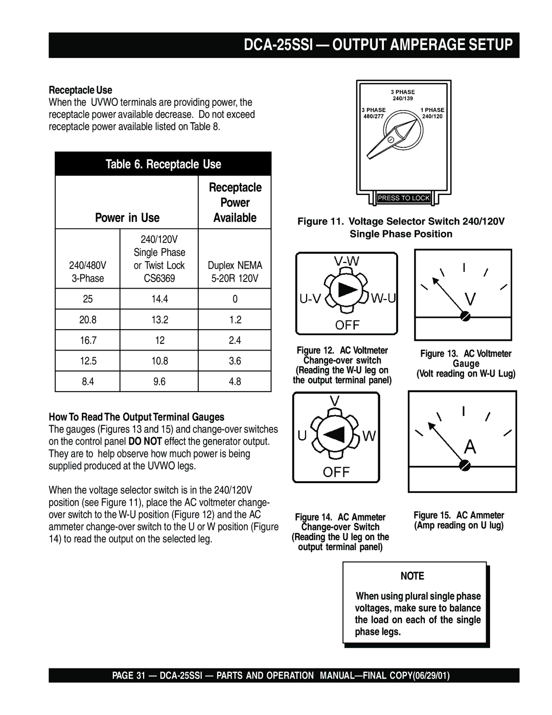
Figure 11. Voltage Selector Switch 240/120V
Single Phase Position
12.5 | 10.8 | 3.6 |
|
|
|
8.4 | 9.6 | 4.8 |
How To Read The Output Terminal Gauges
The gauges (Figures 13 and 15) and
When the voltage selector switch is in the 240/120V position (see Figure 11), place the AC voltmeter change- over switch to the
Figure 12. AC Voltmeter
Change-over switch
(Reading the
Figure 14. AC Ammeter
Change-over Switch
(Reading the U leg on the
output terminal panel)
Figure 13. AC Voltmeter
Gauge
(Volt reading on W-U Lug)
Figure 15. AC Ammeter (Amp reading on U lug)
NOTE
When using plural single phase voltages, make sure to balance the load on each of the single phase legs.
PAGE 31 —