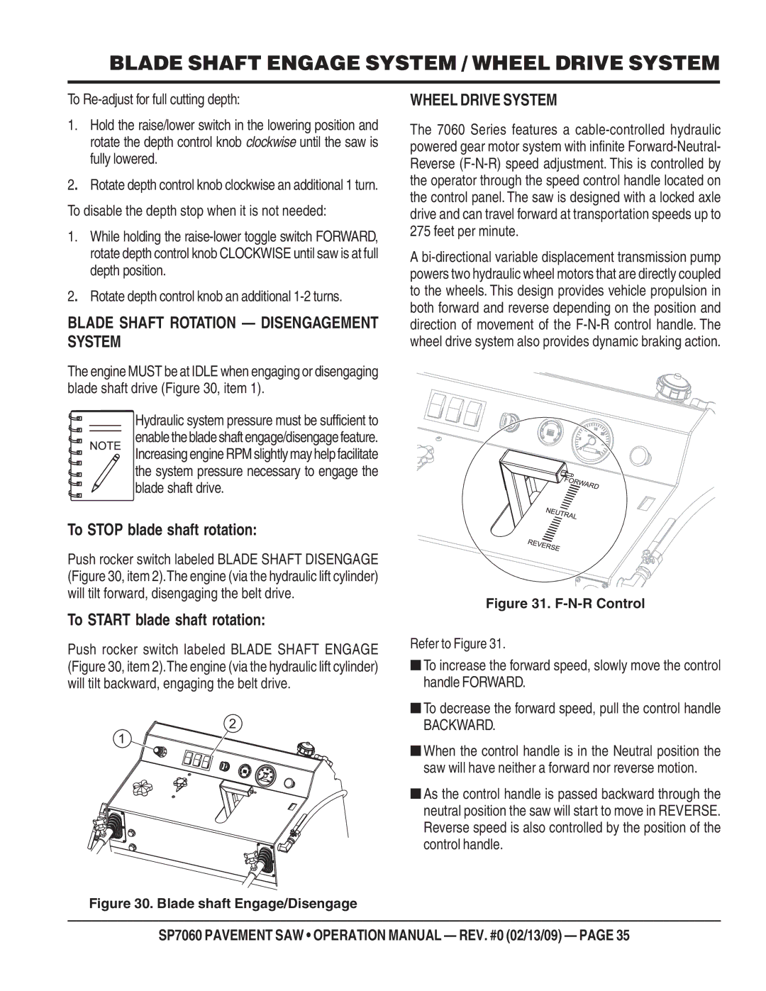
SP706016, SP706026, SP706030, SP706036, SP706020 specifications
Multiquip is a prominent name in the construction equipment industry, known for its innovative and reliable products. Among its versatile offerings, the Multiquip SP706020, SP706016, SP706036, SP706030, and SP706026 stand out as notable concrete pump models. These pumps provide exceptional performance and efficiency, making them ideal for a wide range of applications.Each model in this lineup is engineered for maximum durability and reliability. The SP706020, for instance, features a powerful and efficient hydraulic system that allows for smooth operation and consistent performance, even in demanding conditions. It is designed with a robust frame that can withstand rigorous job site environments, ensuring longevity and reduced maintenance.
The SP706016 stands out with its compact design, making it suitable for smaller job sites while still offering high output and efficiency. This model is equipped with advanced safety features, such as emergency stop buttons and pressure relief valves, ensuring safe operation for the user and surrounding personnel.
Notably, the SP706036 is designed for high-capacity pumping. It is ideal for larger projects that require higher output without compromising on efficiency. Its advanced pumping technology reduces the potential for blockages, enhancing overall productivity. The SP706030 presents a balance between power and size, making it an excellent choice for medium-scale projects.
The SP706026 is notable for its energy-efficient design, which minimizes fuel consumption while providing robust performance. This model reflects Multiquip's commitment to sustainability and cost-effectiveness, allowing contractors to save on operational costs over time.
Across the series, user-friendly controls and adjustable settings provide operators with the flexibility needed to handle various types of concrete mixes and job specifications. Additionally, these models are fitted with high-quality components that enhance performance and reduce wear and tear.
In summary, the Multiquip SP706020, SP706016, SP706036, SP706030, and SP706026 are versatile concrete pumps equipped with cutting-edge technology, ensuring high efficiency, reliability, and safety on any job site. Their various features and specifications make them a valuable addition to any construction operation, catering to diverse project needs while ensuring exceptional performance.

