N-Link – Configuration, Continued…
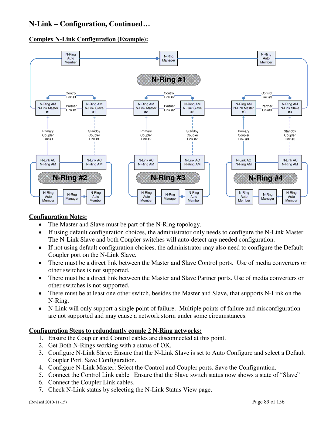
Complex N-Link Configuration (Example):
Auto
Member
Manager
Auto
Member
N-Ring #1
#1
Primary
Coupler
Link #1
Control Link #1
Partner Link #1
#1
Standby
Coupler
Link #1
#2
Primary
Coupler
Link #2
Control Link #2
Partner Link #2
#2
Standby
Coupler
Link #2
#3
Primary
Coupler
Link #3
Control Link #3
Partner
Link#3
#3
Standby
Coupler
Link #3
|
|
|
| |||
Auto |
|
|
|
| Auto | |
Member |
| Manager |
|
|
| Member |
|
|
|
| |||
|
|
|
|
| ||
|
|
|
|
|
|
|
|
|
|
| |||
Auto |
|
|
|
| Auto | |
Member |
| Manager |
|
|
| Member |
|
|
|
| |||
|
|
|
|
| ||
|
|
|
|
|
|
|
N-Ring #4
|
|
|
| |||
Auto |
|
|
|
| Auto | |
Member |
| Manager |
|
|
| Member |
|
|
|
| |||
|
|
|
|
| ||
|
|
|
|
|
|
|
Configuration Notes:
The Master and Slave must be part of the
If using default configuration choices, the administrator only needs to configure the
If not using default configuration choices, the administrator may also need to configure the Default Coupler port on the
There must be a direct link between the Master and Slave Control ports. Use of media converters or other switches is not supported.
There must be a direct link between the Master and Slave Partner ports. Use of media converters or other switches is not supported.
There must be at least one other switch, besides the Master and Slave, that supports
Configuration Steps to redundantly couple 2 N-Ring networks:
1.Ensure the Coupler and Control cables are disconnected at this point.
2.Get Both
3.Configure
4.Configure
5.Connect the Control Link cable. Ensure that the Slave switch status now shows a state of ―Slave‖
6.Connect the Coupler Link cables.
7.Check
(Revised | Page 89 of 156 |