6
DEFINITIONS
for the following symbols used in the venting calculations and examples are:
>- greater than
>- equal to or greater than < - less than
< - equal to or less than
HT - total of both horizontal vent lengths (HR) and offsets (HO) in feet
HR - combined horizontal vent lengths in feet
HO - offset factor: .03 (total degrees of offset - 90°*) in feet
VT - combined vertical vent lengths in feet
ELBOW VENT LENGTH VALUES
| feet | inches |
1° | 0.03 | 0.5 |
15° | 0.45 | 6.0 |
30° | 0.9 | 11.0 |
45° | 1.35 | 16.0 |
90°* | 2.7 | 32.0 |
*the fi rst 90° offset has a zero value and is shown in the formula as
TOP EXIT / HORIZONTAL TERMINATION
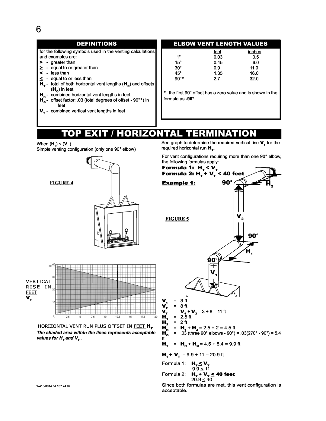
When (HT) < (VT )
Simple venting confi guration (only one 90° elbow)
FIGURE 4
VERTICAL
RISE IN
FEET
VT
HORIZONTAL VENT RUN PLUS OFFSET IN FEET HT
The shaded area within the lines represents acceptable values for HT and VT .
See graph to determine the required vertical rise VT for the required horizontal run HT.
For vent confi gurations requiring more than one 90° elbow, the following formulas apply:
Formula 1: HT < VT
Formula 2: HT + VT < 40 feet
Example 1: | 90° | H2 |
FIGURE 5 | V2 |
90°
H1
90°
V1
V1 | = | 3 ft |
V2 | = | 8 ft |
VT | = V1 + V2 = 3 + 8 = 11 ft | |
H1 | = | 2.5 ft |
H2 | = | 2 ft |
HR | = H1 + H2 = 2.5 + 2 = 4.5 ft | |
HO | = .03 (three 90° elbows - 90°) = .03(270° - 90°) = 5.4 | |
ft |
|
|
HT | = | HR + HO = 4.5 + 5.4 = 9.9 ft |
HT + VT = 9.9 + 11 = 20.9 ft
Formula 1: HT < VT 9.9 < 11
Formula 2: HT + VT < 40 feet 20.9 < 40
Since both formulas are met, this vent configuration is acceptable.