..
I 2(
|
|
|
|
|
|
|
| SECTION | 200 | HARDWARE | INSTALLATION |
|
|
|
|
|
|
|
|
| ||||||||
210 | Installation | of | the | Key | Service | Unit |
|
| 210.2 | Floor | Mounting | the |
| KSU |
|
|
|
|
|
| ||||||||
210.1 | Wall | Mounting the | KSU |
|
|
|
|
|
| 1. | The | same | bracket | that | is provided | for | wall | mounting | ||||||||||
1. | The |
| KSU | is | supplied | with a wall mounting |
| can also be used to anchor a floor mounted KSU. Set | ||||||||||||||||||||
|
| the bracket on a level surface with the 6 screw holes | ||||||||||||||||||||||||||
| bracket. The bracket should be mounted on a back- |
| ||||||||||||||||||||||||||
|
| down and the securing screw facing up and the floor | ||||||||||||||||||||||||||
| board secured in a manner capable of holding the |
| ||||||||||||||||||||||||||
|
| mounting slot to the right. |
|
|
|
|
|
| ||||||||||||||||||||
| weight of the KSU. With the mounting tabs of the |
|
|
|
|
|
|
| ||||||||||||||||||||
|
|
|
|
|
|
|
|
|
|
|
|
|
|
|
| |||||||||||||
| bracket | facing | upward, | install | appropriate | screws | into | 2. | Loosen | the securing | screw | located | in | the | rear | right | ||||||||||||
| the 6 holes | of | the | bracket. | Loosen the | securing screw |
| position | of | the | bracket. |
|
|
|
|
|
|
| ||||||||||
| located in the upper right position of the bracket. |
| 3. | Engage the | mounting | tabs on the | bracket into the slots | |||||||||||||||||||||
|
|
|
|
|
|
|
|
|
|
|
|
|
| |||||||||||||||
2. | Align the mounting | slots | of the KSU with the mount- |
| on | the | bottom | of | the |
| KSU | and | push | forward to | seat ’ | |||||||||||||
| ing tabs of the bracket, | and push down to seat the |
| the | KSU securely. |
|
|
|
|
|
|
|
|
| ||||||||||||||
KSU securely. |
|
|
|
|
|
|
|
|
|
| 4. Locate and tighten the securing screw through the hold | |||||||||||||||||
|
|
|
|
|
|
|
|
|
|
|
|
|
| |||||||||||||||
3. | Remove | the | front | cover | of | the | KSU, | and | locate | and |
| provided | on the | bottom |
| panel | of the | KSU. |
|
| ||||||||
tighten the securing .screw through the hole provided |
|
|
|
|
|
|
|
|
|
|
|
|
|
|
| |||||||||||||
above the J 1 connector. |
|
|
|
|
|
|
|
|
|
|
|
|
|
|
|
|
|
|
|
|
|
|
| |||||
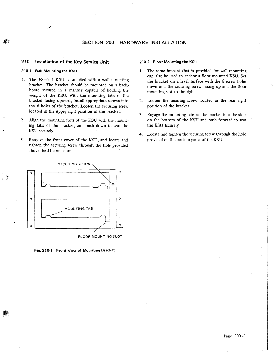
SECURING SCREW \
\
0
0
FLOOR MOUNTING SLOT
Fig. 210-l Front View of hbunting Bracket
Page
