On the CPU-S KTU is a momentary switch for system reset. Depressing the reset switch causes any program changes to enter the working program and interrupts all system operation in progress.
2.CLK-S KTU
When DCI-S KTU(s) is installed ensure the switches SW1 and SW2 on the CLK-S KTU are set to appro- priate positions. Refer to Table 230-2 below. The switch settings are subject to the dialing specifications of the CO or PBX. The switches have been set by the
manufacturer at 1Opps dial speed and at 39% make ratio.
Table 230-2 Rotary Dial Pulse Signalling Switch Settings
Dial Speed SW1
; :z; /
230.4installing Optional KTUs
1.PBS-S KTU
Install PBS-S KTU in ES-6-1 KSU when External
Paging,Busy Lamp Field and/or Security options are
required. Refer to Section 250.2 “EB-6-1 Installa-
tion” for BLF connection. When installing External Paging and/or Security options, see Section 260, Instal- ling Options”.
7DPH-S KTU
When a DPH-S KTU is installed in the ES-6-l KSU,
two DP-6-1 can be used as Door Phone or Monitor Phone separately.
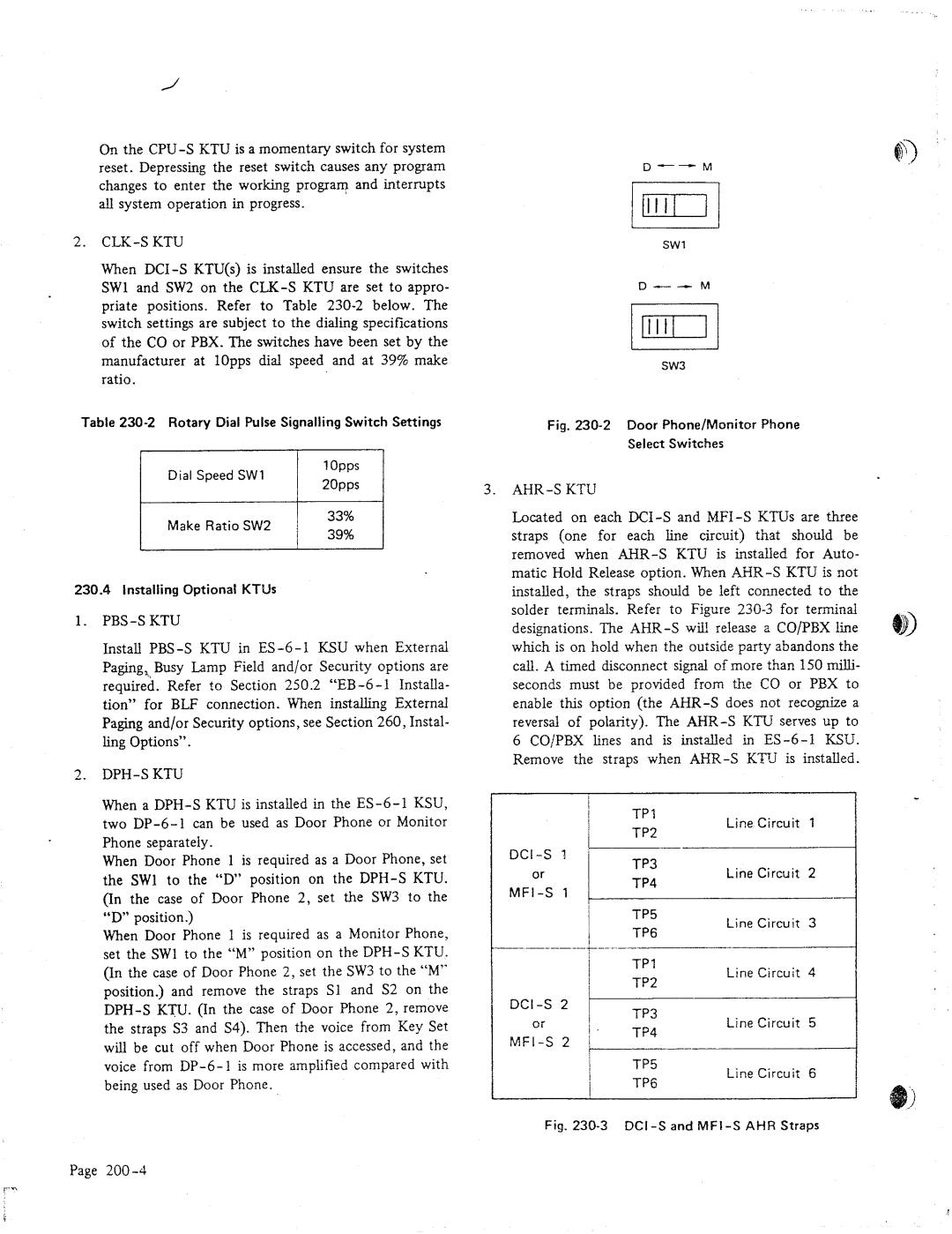
When Door Phone 1 is required as a Door Phone, set the SW1 to the “D” position on the DPH-S KTU. (In the case of Door Phone 2, set the SW3 to the “D” position.)
When Door Phone 1 is required as a Monitor Phone, set the SW1 to the “M” position on the DPH-S KTU. (In the case of Door Phone 2, set the SW3 to the “M” position.) and remove the straps Sl and S2 on the DPH-S KTU. (In the case of Door Phone 2, remove the straps S3 and S4). Then the voice from Key Set will be cut off when Door Phone is accessed, and the
voice from DP-6-l is more amplified compared with being used as Door Phone.
D--M
SW1
Fig. 230-2 Door Phone/Monitor Phone
Select Switches
3.AHR-S KTU
Located on each DCI-S and MFI-S KTUs are three straps (one for each line circuit) that should be removed when AHR-S KTU is installed for Auto- matic Hold Release option. When AHR-S KTU is not installed, the straps should be left connected to the solder terminals. Refer to Figure 230-3 for terminal designations. The AHR-S will release a CO/PBX line which is on hold when the outside party abandons the call. A timed disconnect signal of more than 150 milli- seconds must be provided from the CO or PBX to enable this option (the AIIR-S does not recognize a reversal of polarity). The AHR-S KTU serves up to
6 CO/PBX lines and is installed in ES-6-l KSU. Remove the straps when AHR-S KTrJ is installed.
DCI-S 1
or
MFI-S 1
Line Circuit 3
Line Circuit 6
Fig. 230-3 DCI-S and MFI-S AHR Straps