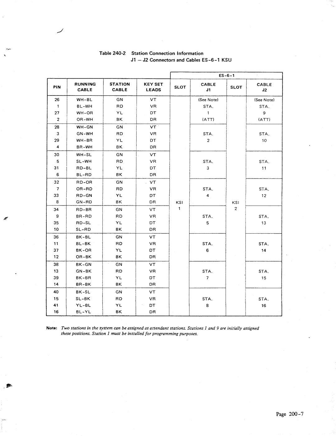
Table
Jl - 52 Connectors and Cables
| PIN | RUNNING | STATION | KEY SET |
| CABLE | CABLE | LEADS | |
|
| |||
| 26 | GN | VT | |
| 1 | RD | VR | |
| 27 | YL | DT | |
| 2 | BK | DR | |
| 28 | GN | VT | |
| 3 | RD | VR | |
| 29 | YL | DT | |
| 4 | BK | DR | |
| 30 | GN | VT | |
| 5 | RD | VR | |
| 31 | YL | DT | |
| 6 | BK | DR | |
| 32 | GN | VT | |
| 7 | RD | VR | |
| 33 | YL | DT | |
| 8 | BK | DR | |
| 34 | GN | VT | |
P | 9 | RD | VR | |
|
|
|
| |
| 35 | YL | DT | |
| 10 | BK | DR | |
| 36 | GN | VT | |
| 11 | RD | VR | |
| 37 | YL | DT | |
| 12 | BK | DR | |
| 38 | GN | VT | |
| 13 | RD | VR | |
| 39 | YL | DT | |
| 14 | BK | DR | |
| 40 | GN | VT | |
| 15 | RD | VR | |
| 41 | YL | DT | |
| 16 | BK | DR |
CABLE | CABLE |
SLOT | SLOT |
Jl | 92 |
(See Note) | (See Note) |
STA. | STA. |
1 | 9 |
(ATT) | (ATT) |
STA. | |
STA. | |
2 | 10 |
STA. | STA. |
3 | 17 |
STA. | STA. |
4 | 12 |
KSI | KS! |
1 |
|
STA. |
|
5 |
|
STA. |
|
6 |
|
STA. | STA. |
7 | 15 |
STA. | STA. |
8 | 16 |
Note: Two stations in rhe sysrem can be assigned as attendant srarions. Stations 1 and 9 are initialIy assigned
these positions. Sration 1 must be insralled for programming purposes.
Page