NETGEAR, Inc
USA
Statement of Conditions
Trademarks
EN 55 022 Decla0ration of Conformance
Bestätigung des Herstellers/Importeurs
Certificate of the Manufacturer/Importer
VCCI-2 Statement
Customer Support
Frontmat.fm Page iv Tuesday, October 10, 2000 311 PM
Contents
Chapter Router Installation and Connection
Chapter Router Configuration
Chapter Configuration for Internet Access
Chapter Remote Node Configuration
Chapter Dial-In Configuration
Chapter TCP/IP Configuration
Chapter System Maintenance
Chapter Troubleshooting
Appendix D Using the Protocol Analyzer and Trace Tools
Appendix a Technical Specifications
Appendix B Ordering Isdn Lines
Appendix C Isdn Clearing Codes
RH348TOC.fm Page x Tuesday, October 10, 2000 312 PM
Figures
Figure D-1
Tables
Abbreviations Used in Menu 21.1 Filter Rules Summary
Table B-1
Preface
Purpose
Audience
Congratulations on your purchase of the Netgear
Conventions
Special Message Formats
Use of Enter, Type, and Press
This section describes the conventions used in this guide
Related Publications
Other Conventions
This guide uses the following typographical conventions
DOS file and directory names
Preface.fm Page xviii Tuesday, October 10, 2000 314 PM
Chapter Introduction
Features
About the Router
Key Features
Isdn Support
Multilink PPP Support
TCP/IP Support
Security
PAP and Chap Authentication
Management Support
Basic Router Concepts
What is a Router?
Routing Information Protocol
IP Addresses and the Internet
Is normally written as
Three Main Address Classes
Netmask
Address remains
ANDed with
Equals
Subnet Addressing
Example of Subnetting a Class B Address
Netmask Notation Translation Table for One Octet
Netmask Formats
Private IP Addresses
Dotted-Decimal Masklength
Single IP Address Operation Using NAT
Illustrates a single IP address operation
Address Resolution Protocol
Domain Name Server
IP Configuration by Dhcp
Intro.fm Page 16 Tuesday, October 10, 2000 315 PM
Chapter Router Installation and Connection
Package Contents
Isdn Services Checklist
Or incoming call bumping
Network Checklist
Connecting the Router
Front Panel of Model RT328 Router
LED Descriptions
Label Activity Description
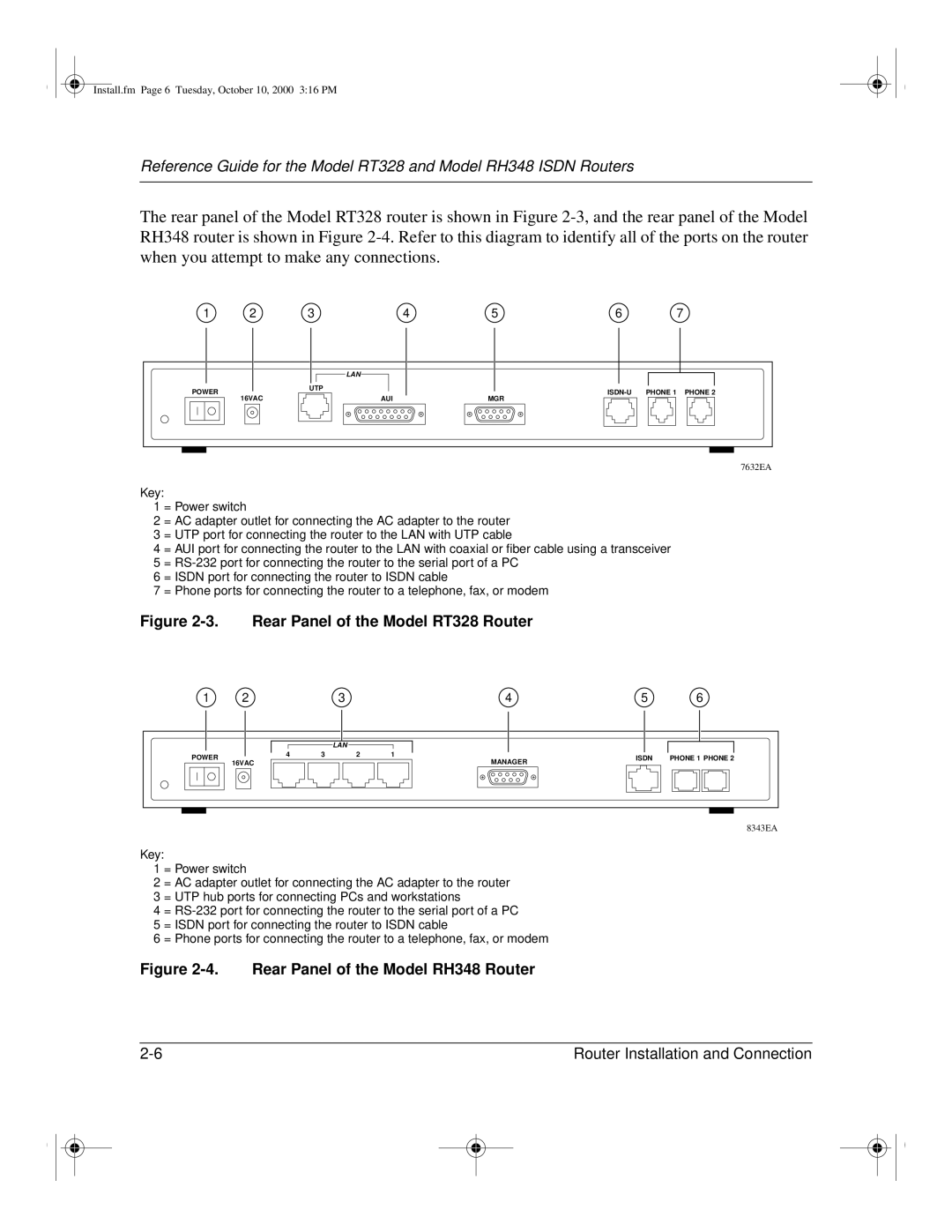
Rear Panel of the Model RT328 Router
Connecting to the Isdn Port
Connecting the Serial Cable Optional
Connecting the Ethernet Cable
Connecting a Telephone, Fax, or Modem
Connecting to the Hub Ports in the Model RH348 Router
Connecting the Power Adapter
Connecting Through a Serial Port
Connecting for Configuration
Connecting Through a Telnet Connection
System timeout
Chapter Router Configuration
Configuration Methods
Powering on the Router
To continue
Navigating the Manager
Manager Menu Commands
Action Description
Manager Main Menu is illustrated in Figure
Manager Main Menu
Manager Menu Summary
Describes the top-level Manager menus
Manager Menu Summary
Number Menu Title Description
General Setup Menu
Menu 1 General Setup
Isdn Setup Menu Parameters for North America
Isdn Menus
North American Isdn Menu
System can make an outgoing call or answer an incoming call
Shows Menu 2 Isdn Setup for North America
DSS1 Isdn Menu
Isdn Setup Field Descriptions
Shows Menu 2 Isdn Setup for DSS1
General Setup Menu
Ethernet Setup
Ethernet General Setup Menu Fields
Dhcp and TCP/IP Setup
Menu 3 Ethernet Setup Menu Fields
RIP Direction
Manager Password Setup
To change the Manager password
Chapter Configuration for Internet Access
Information Checklist
To configure your router for Internet access
Internet Access Configuration
If you do not have this data, you can leave it blank
Enter your password in the My Password field
Configuration for Single User Account
Single User Account Server IP Addr
Chapter Remote Node Configuration
To create a remote node
Menu 11.1 Remote Node Profile Fields
Submenu
Editing PPP Options
Press Esc at any time to cancel your selections
To edit PPP options
Fields in Menu 11.2 Remote Node PPP Options
Bandwidth on Demand
Relationship Between BTR and MTR
Default Dial-In Setup
Chapter Dial-In Configuration
Fields in Menu 13 Default Dial-in Setup
Multiple Link Options Max Trans Rate
Dial-In Users Setup
Lists and describes the fields in the Edit Dial-in User menu
Fields in Menu 14.1 Edit Dial-in User
Dialin.fm Page 6 Tuesday, October 10, 2000 320 PM
Chapter TCP/IP Configuration
LAN-to-LAN Application
To set the protocol-dependent parameters
Remote Node Setup
Fields in Menu 11.1 Remote Node Profile Fields
Menu 11.3 Remote Node Network Layer Options Fields
Static Route Setup
RIP
Edit IP Static Route Menu Fields
Tcpip.fm Page 6 Tuesday, October 10, 2000 324 PM
Chapter Filter Configuration
Outgoing Packet Filtering Process
Router Filter Structure
Configuring a Filter Set
Abbreviations Used if Filter Type Is IP
Abbreviations Used in Menu 21.1 Filter Rules Summary
Abbreviation Description
TCP/IP Filter Rule
Configuring a Filter Rule
Abbreviations Used if Filter Type Is GEN
TCP/IP Filter Rule Menu Fields
Field Descriptions
Filter.fm Page 6 Tuesday, October 10, 2000 325 PM
Generic Filter Rule
Generic Filter Rule Menu Fields
Applying a Filter Set
Reducing Unnecessary Calls by Windows
Background activity Some cases, this NetBIOS
Diagnosing the Situation
05 00
Protocol 17, or 11h =UDP
05 00 1F 11 CC 9D 8D FB 17
Bold characters denote source IP 141.251.23.18=local PC
Implementing the Filter
Menu 21 Filter Set Configuration
Shows Menu 21.1.1 TCP/IP Filter Rule
Filter Rules Summary Menu
When you finish, restart the router
Applying the Filter
Chapter System Maintenance
System Maintenance Status Menu Fields
Command Field Name Description
System Status
CLU
Terminal Baud Rate
Packet Examples
View Error Log
System Maintenance Log and Trace Menu Fields
Command Field
Log and Trace
Field Command Description
System Maintenance Syslog and Accounting Menu Fields
You must configure the parameters to activate syslog Table
System Maintenance Diagnostic Menu Fields
Diagnostic Menu
Isdn Tools
TCP/IP Tools
Trace Display for a Successful TCP/IP Protocol Connection
Back Up Configuration
Restore Configuration
System Tools
Message is displayed asking if you want to continue
Blacklist
Call Control
Budget Management
Call History
Call Control Parameters
Sysmaint.fm Page 12 Tuesday, October 10, 2000 326 PM
Chapter Troubleshooting
Basic Functioning
Troubleshooting the Isdn Line
Test LED
LAN Link LED
Should contact technical support
Isdn Loopback Test
Isdn Initialization or Reset
Code Numbers for Failed Isdn Initialization
Troubleshooting a TCP/IP Network Using a Ping Utility
Testing the LAN Path to Your Router
You should see a message like this one
If the path is working, you see this message
Testing the Path from Your PC to a Remote Device
Troubleshooting a Remote Node or ISP Connection
Primary Phone # Secondary Phone # Transfer Rate
Troubleshooting a Remote User Connection
Testing the Phone Ports
Troubleshooting the Manager Interface
Restoring the Default Configuration and Password
Restart the router
Appendix a Technical Specifications
General Specification
WAN Protocols PPP, Multilink PPP, Bacp
Isdn Standard
Dimensions 253 by 181 by 35 mm 95 by 7.1 by 1.4 Weight
Operating temperature To 40 C Operating humidity
Interface, RJ-45 NT1 built-in
Analog
Ordering the Line
Appendix B Ordering Isdn Lines
To order your Isdn line
Provisioning for Switches in North America
Provisioning for AT&T 5ESS Switch
Table B-1 Switch Types Supported
Switch Type Region No. of Phone #s No. of SPIDs
Provisioning Feature Setting
Provisioning for Northern Telecom Switch
Appbisdn.fm Page 5 Tuesday, October 10, 2000 329 PM
Appbisdn.fm Page 6 Tuesday, October 10, 2000 329 PM
Appendix C Isdn Clearing Codes
Clearing Codes
Table C-1 lists the Isdn call clearing codes
Table C-1 Isdn Call Clearing Codes
Table C-1. Isdn Call Clearing Codes
Diagnostic Process
To begin problem diagnosis
Isdn Protocol Analyzer
To invoke the EPA
Appdtool.fm Page 3 Tuesday, October 10, 2000 331 PM
Figure D-1. Isdn Protocol Analyzer Display
Packet Tracing
Appdtool.fm Page 6 Tuesday, October 10, 2000 331 PM
Figure D-2
Trace Screen
Packet Trace Display Format
Figure D-3. Packet Trace Display Definitions
Glossary
Bearer Service
Integrated Services
Data Over Speech
Dynamic Host
Glossary
Password
Service Point-to-Point
Service Profile
Plain Old Telephone
Index
Configuration
Domain name server, using DSS1 Dynamic NAT
Isdn F/W Version field, System Maintenance menu
PPP
TCP/IP
Value field, Generic Filter Rule menu