User Guide
Chapter 2 - Your VOIP ATA at a glance
The VOIP ATA may have different ports and LEDs. Let’s take a look at the different options. Depending upon your model, it may have some or all of the features listed below
2.1Ports and buttons
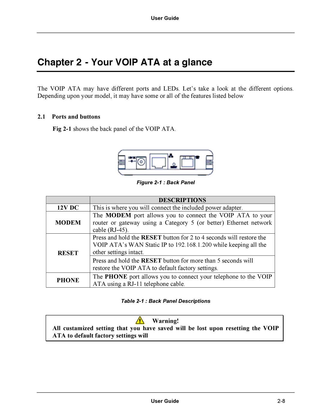
Fig
| Figure | |
|
| |
| DESCRIPTIONS | |
12V DC | This is where you will connect the included power adapter. | |
MODEM | The MODEM port allows you to connect the VOIP ATA to your | |
router or gateway using a Category 5 (or better) Ethernet network | ||
| cable | |
| Press and hold the RESET button for 2 to 4 seconds will restore the | |
| VOIP ATA’s WAN Static IP to 192.168.1.200 while keeping all the | |
RESET | other settings intact. | |
| Press and hold the RESET button for more than 5 seconds will | |
| restore the VOIP ATA to default factory settings. | |
PHONE | The PHONE port allows you to connect your telephone to the VOIP | |
ATA using a | ||
| ||
| Table |
Warning!
All custamized setting that you have saved will be lost upon resetting the VOIP ATA to default factory settings will
User Guide |