Contents
Commercial Series
Page
CM200/CM300/PM400 Radios
Foreword
Table of Contents
Transceiver Performance Testing
Glossary
This page Intentionally Left Blank
Safety Information
Product Safety and RF Exposure Compliance
This page is Intentionally Blank
Introduction
Replacement Parts Ordering
Radio Model Information
This page Intentionally Left Blank
Chapter
Preventive Maintenance
Cleaning Procedures
Introduction
Cleaning Internal Circuit Boards and Components
Safe Handling of Cmos and Ldmos Devices
Disassembling and Reassembling the Radio General
Repair Procedures and Techniques General
Parts Replacement and Substitution
Rigid Circuit Boards
Radio Disassembly Detailed
Volume Knob Removal
Control Head Removal
3Flat Cable Removal
Top Cover Removal
5Top Cover Removal Chassis Horizontal
Main Shield Removal
PA Shield and DC Cable Removal
PA Clip and Main PCB Removal for Low Power Models
8PA Shield and DC Cable Removal for High Power Models
Main PCB Removal for High Power Models
10PA Clip and Main PCB Removal for High Power Models
Disassembly of Control Head CM200
PCB
Disassembly of Control Heads CM300/PM400
12Control Head Housing Removal CM300/PM400
Radio Assembly
Chassis Assembly for Low Power Models
Chassis Assembly for High Power Models
Control Heads Assembly
Control Head Fitting
Option Board Installation
Radio Exploded Mechanical Views and Parts Lists
Radio Assembly 1-25 W Models
Item No Description Part Number
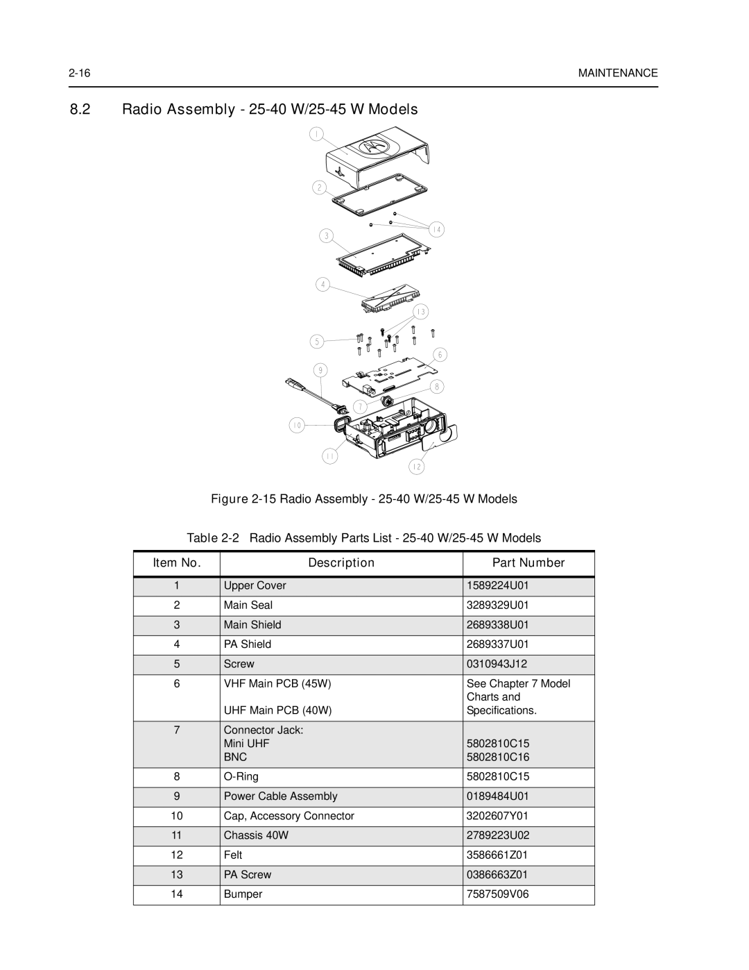
Radio Assembly 25-40 W/25-45 W Models
Control Head CM200
Item no Description
Control Head CM300/PM400
Service Aids
Motorola Part Description Application
Test Equipment
Programming/Test Cable RKN4083
FLO830308-0
20Pin Configuration of FKN8113
Adapter Cable FKN8113
General
Setup
Service Monitor Test Set Power Supply
Table Number Title
HSS
RF Test Mode
To enter test mode display radios
CMP
Test Mode
Test Name Communications Analyzer Radio Test Set Comment
TPL
Dtmf
PL/DPL
DPL
Sinad
This page Intentionally Left Blank
CPS Programming/Flashing Setup with RIB
Description Kit Number
CPS
CPS Programming/Flashing Setup Ribless
CPS Programming Setup with RIB with Telco Connector
CPS Programming Setup with RIB Accessory Connector
CPS Programming Setup with RIB
Radio Tuning Setup
Initial Test Equipment Control Settings
Service Monitor Test Set Power Supply
Power UP SELF-TEST
Error Codes
Power UP SELF-TEST
VHF
Accessories
Antennas
UHF
Alarms and Accessories
Audio
Cables
Control Station
Public Address
Mounting
Data CES Wireless Technologies
Peripherals
Accessory Connector Pin Function
SCI
Microphone Connector Pin Function
SCI/DTMF
VHF2, 1-25 W, 146-174 MHz
Low Power Radios
146-174 MHz CM200/CM300/PM400 Model Chart
Model Description
AAM50RNC9AA1A
438-370 MHz CM200/CM300/PM400 Model Chart
UHF2, 1-25 W, 438-470 MHz
AAM50RNF9AA1AN
General
Specifications
Specification
ESD
Transmitter
Receiver
VHF1, 25-45 W, 136-162 MHz
High Power Radios
136-162 MHz CM300 Model Chart
VHF2, 25-45 W, 146-174 MHz
AAM50RPC9AA1A
438-470 MHz CM200/CM300/PM400 Model Chart
UHF2, 25-40 W, 438-470 MHz
AAM50RPF9AA1AN
465-495 MHz PM400 Model Chart
UHF3, 25-40 W 465-495 MHz
AAM50SPF9AA3AN
VHF1 VHF2 UHF2 UHF3
35 ∝V @ 12.5 kHz ∝V @ 25 kHz
MIL Standards
MIL-STD
Glossary of Terms
Term Definition
PLL
Reset
OSW
PTT
VCO
Vcobic
Vswr
This page Intentionally Left Blank
Page
6802966C15