5.1.1 Configuration and Option Register (COR)
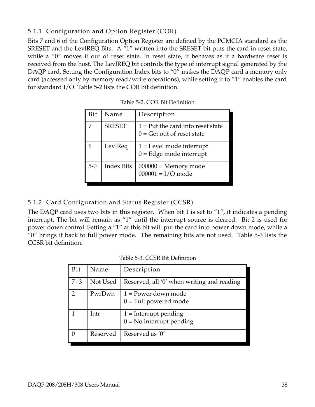
Bits 7 and 6 of the Configuration Option Register are defined by the PCMCIA standard as the SRESET and the LevlREQ Bits. A “1” written into the SRESET bit puts the card in reset state, while a “0” moves it out of reset state. In reset state, it behaves as if a hardware reset is received from the host. The LevlREQ bit controls the type of interrupt signal generated by the DAQP card. Setting the Configuration Index bits to “0” makes the DAQP card a memory only card (accessed only by memory read/write operations), while setting it to “1” enables the card for standard I/O. Table
Table
| Bit | Name | Description |
| ||
|
| |||||
|
|
|
|
|
| |
| 7 | SRESET | 1 | = Put the card into reset state |
|
|
|
|
| 0 | = Get out of reset state |
| |
|
|
|
|
|
| |
| 6 | LevlReq | 1 | = Level mode interrupt |
|
|
|
|
| 0 | = Edge mode interrupt |
| |
|
|
|
|
| ||
| Index Bits | 000000 = Memory mode |
|
| ||
|
|
| 000001 = I/O mode |
| ||
|
|
|
|
|
|
|
|
|
|
|
|
|
|
5.1.2 Card Configuration and Status Register (CCSR)
The DAQP card uses two bits in this register. When bit 1 is set to “1”, it indicates a pending interrupt. The bit will remain as “1” until the interrupt source is cleared. Bit 2 is used for power down control. Setting a “1” at this bit will put the card into power down mode, while a “0” brings it back to full power mode. The remaining bits are not used. Table
Table
| Bit | Name | Description |
| ||
|
| |||||
|
|
|
|
| ||
| Not Used | Reserved, all ‘0’ when writing and reading |
|
| ||
|
|
|
|
|
| |
| 2 | PwrDwn | 1 | = Power down mode |
|
|
|
|
| 0 | = Full powered mode |
| |
|
|
|
|
|
| |
| 1 | Intr | 1 | = Interrupt pending |
|
|
|
|
| 0 | = No interrupt pending |
| |
|
|
|
|
| ||
| 0 | Reserved | Reserved as ‘0’ |
|
| |
|
|
|
|
|
|
|
|
|
|
|
|
|
|
38 |
