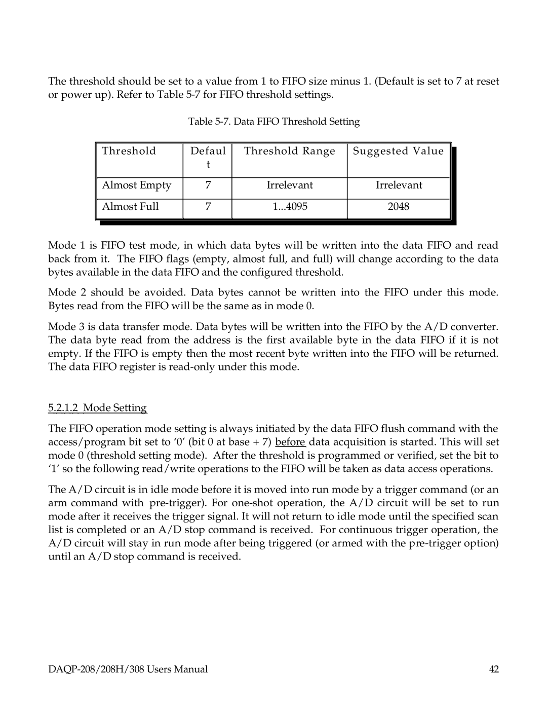
The threshold should be set to a value from 1 to FIFO size minus 1. (Default is set to 7 at reset or power up). Refer to Table
Table 5-7. Data FIFO Threshold Setting
| Threshold | Defaul | Threshold Range | Suggested Value |
| |
|
| |||||
|
| t |
|
|
|
|
|
|
|
|
|
| |
| Almost Empty | 7 | Irrelevant | Irrelevant |
|
|
|
|
|
|
|
|
|
| Almost Full | 7 | 1...4095 | 2048 |
|
|
|
|
|
|
|
|
|
|
|
|
|
|
|
|
Mode 1 is FIFO test mode, in which data bytes will be written into the data FIFO and read back from it. The FIFO flags (empty, almost full, and full) will change according to the data bytes available in the data FIFO and the configured threshold.
Mode 2 should be avoided. Data bytes cannot be written into the FIFO under this mode. Bytes read from the FIFO will be the same as in mode 0.
Mode 3 is data transfer mode. Data bytes will be written into the FIFO by the A/D converter. The data byte read from the address is the first available byte in the data FIFO if it is not empty. If the FIFO is empty then the most recent byte written into the FIFO will be returned. The data FIFO register is
5.2.1.2 Mode Setting
The FIFO operation mode setting is always initiated by the data FIFO flush command with the access/program bit set to ‘0’ (bit 0 at base + 7) before data acquisition is started. This will set mode 0 (threshold setting mode). After the threshold is programmed or verified, set the bit to ‘1’ so the following read/write operations to the FIFO will be taken as data access operations.
The A/D circuit is in idle mode before it is moved into run mode by a trigger command (or an arm command with
42 |
