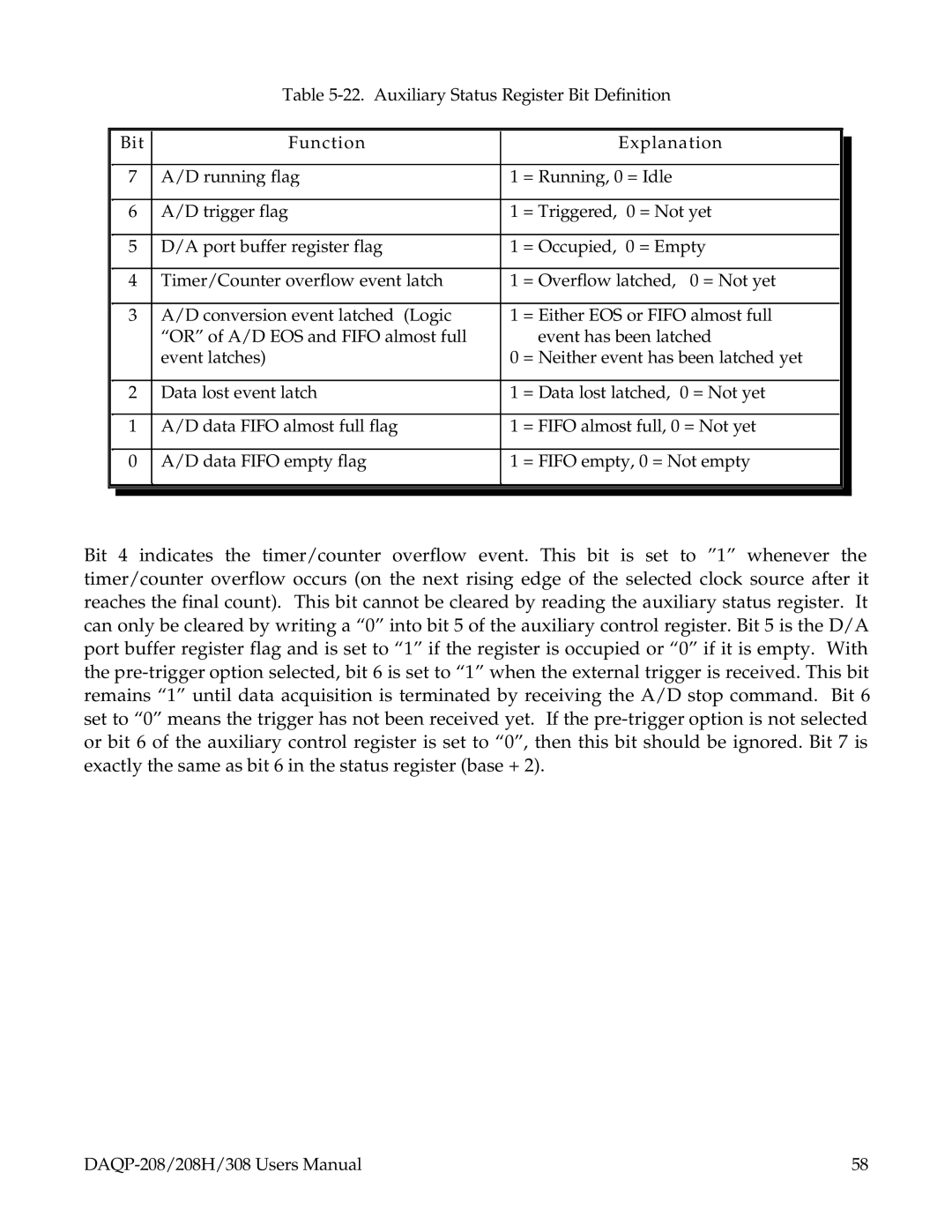
Table
| Bit | Function |
| Explanation |
| |
|
|
| ||||
|
|
|
|
|
| |
| 7 | A/D running flag | 1 | = Running, 0 = Idle |
|
|
|
|
|
|
|
| |
| 6 | A/D trigger flag | 1 | = Triggered, 0 = Not yet |
|
|
|
|
|
|
|
| |
| 5 | D/A port buffer register flag | 1 | = Occupied, 0 = Empty |
|
|
|
|
|
|
|
| |
| 4 | Timer/Counter overflow event latch | 1 | = Overflow latched, 0 = Not yet |
|
|
|
|
|
|
|
| |
| 3 | A/D conversion event latched (Logic | 1 | = Either EOS or FIFO almost full |
|
|
|
| “OR” of A/D EOS and FIFO almost full |
| event has been latched |
| |
|
| event latches) | 0 | = Neither event has been latched yet |
| |
|
|
|
|
|
| |
| 2 | Data lost event latch | 1 | = Data lost latched, 0 = Not yet |
|
|
|
|
|
|
|
| |
| 1 | A/D data FIFO almost full flag | 1 | = FIFO almost full, 0 = Not yet |
|
|
|
|
|
|
|
| |
| 0 | A/D data FIFO empty flag | 1 | = FIFO empty, 0 = Not empty |
|
|
|
|
|
|
|
|
|
|
|
|
|
|
|
|
Bit 4 indicates the timer/counter overflow event. This bit is set to ”1” whenever the timer/counter overflow occurs (on the next rising edge of the selected clock source after it reaches the final count). This bit cannot be cleared by reading the auxiliary status register. It can only be cleared by writing a “0” into bit 5 of the auxiliary control register. Bit 5 is the D/A port buffer register flag and is set to “1” if the register is occupied or “0” if it is empty. With the
58 |