Controls &
1TRACK indicator
Appears when the CD input source is selected.
2MEMORY indicator (21)
Lights up when memory playback is used.
3RANDOM indicator (21)
Lights up when random playback is used.
4REPEAT indicator (21)
Lights up when repeat playback is used.
5FM STEREO indicator (22)
Lights up when tuned to a stereo FM station.
6AUTO indicator (22)
Lights up when auto stereo tuning is used.
7Tuned indicator (22)
Lights up when the
8MUTING indicator (25)
Lights up when the
9RDS indicator (17, 23)
Lights up when the
0A & B speaker indicators (19)
Indicator A lights up when speaker set A is on. Indicator B lights up when speaker set B is on.
ASLEEP indicator (28)
Lights up when the Sleep function has been set.
BMessage area
Various information is displayed here.
C Play/Pause /![]()
![]() indicators (20)
indicators (20)
Light up for playback and pause.
DTIMER indicators (27)
Light up when a timer has been set.
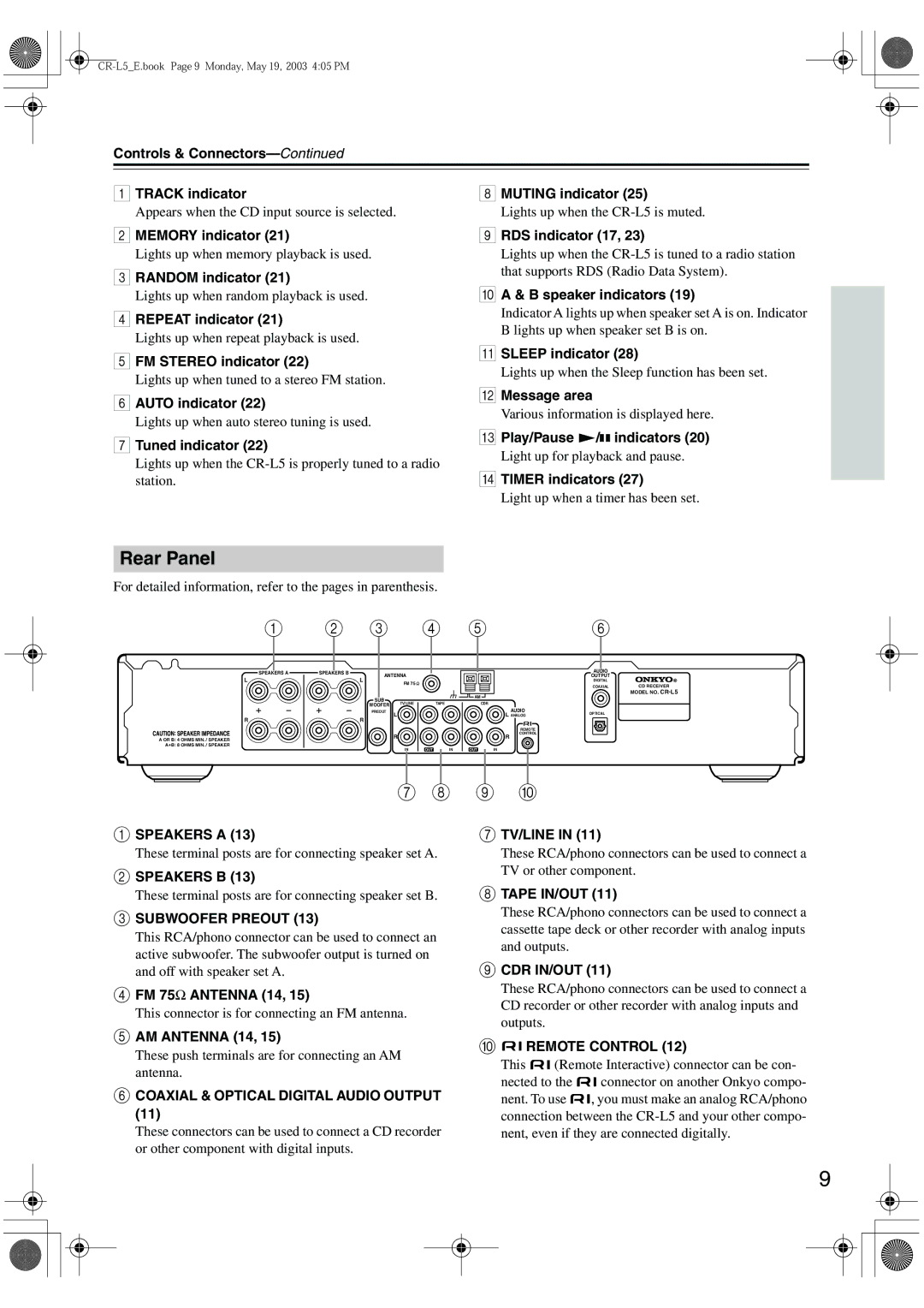
Rear Panel
For detailed information, refer to the pages in parenthesis.
1 | 2 | 3 | 4 | 5 | 6 |
SPEAKERS A
L
R
A OR B: 4 OHMS MIN. / SPEAKER
A+B: 8 OHMS MIN. / SPEAKER
SPEAKERS B |
|
|
|
|
|
| AUDIO |
|
ANTENNA |
|
|
|
| OUTPUT |
| ||
|
|
|
|
|
| |||
| L | FM 75 |
|
|
|
| DIGITAL |
|
|
|
|
|
|
| COAXIAL | CD RECEIVER | |
|
|
|
|
|
|
| ||
|
|
|
|
| AM |
|
| MODEL NO. |
| SUB |
|
|
|
|
|
| |
| TV/LINE |
| TAPE |
| CDR |
|
| |
| WOOFER |
|
|
|
| |||
|
|
|
|
| AUDIO |
|
| |
| PREOUT | L |
|
|
| OPTICAL |
| |
| R |
|
|
| L ANALOG |
| ||
|
|
|
|
|
|
|
| |
|
|
|
|
|
| REMOTE |
|
|
|
| R |
|
|
| CONTROL |
|
|
|
|
|
|
| R |
|
| |
|
| IN | OUT | IN | OUT | IN |
|
|
7 8 9 J
ASPEAKERS A (13)
These terminal posts are for connecting speaker set A.
BSPEAKERS B (13)
These terminal posts are for connecting speaker set B.
CSUBWOOFER PREOUT (13)
This RCA/phono connector can be used to connect an active subwoofer. The subwoofer output is turned on and off with speaker set A.
DFM 75Ω ANTENNA (14, 15)
This connector is for connecting an FM antenna.
EAM ANTENNA (14, 15)
These push terminals are for connecting an AM antenna.
FCOAXIAL & OPTICAL DIGITAL AUDIO OUTPUT (11)
These connectors can be used to connect a CD recorder or other component with digital inputs.
GTV/LINE IN (11)
These RCA/phono connectors can be used to connect a TV or other component.
HTAPE IN/OUT (11)
These RCA/phono connectors can be used to connect a cassette tape deck or other recorder with analog inputs and outputs.
ICDR IN/OUT (11)
These RCA/phono connectors can be used to connect a CD recorder or other recorder with analog inputs and outputs.
J
 REMOTE CONTROL (12)
This ![]()
![]() (Remote Interactive) connector can be con-
(Remote Interactive) connector can be con-
nected to the ![]()
![]() connector on another Onkyo compo-
connector on another Onkyo compo-
nent. To use ![]()
![]() , you must make an analog RCA/phono connection between the
, you must make an analog RCA/phono connection between the
9