TX-SR603X
Important Safety Instructions
Avis
Power
Precautions
For models having a power cord with a polarized plug
FCC Information for User
Make sure you have the following accessories
Supplied Accessories
Precautions
If in any doubt, consult a qualified electrician
Audio/Video
Features
Amplifier
FM/AM/XM Tuner
Table of Contents
Table of Contents
Front & Rear Panels
Front Panel
Front & Rear Panels
Display
These terminals are for connecting speakers in Zone
These push terminals are for connecting an AM antenna
This jack is for connecting an FM antenna
Rear Panel
Subwoofer jack is for connecting a pow- ered subwoofer
PRE OUT
Remote Controller
Installing the Batteries
Using the Remote Controller
Remote Controller
About the Remote Controller Modes
RECEIVER/TAPE Mode
Tape mode
Listening Mode / buttons
Remote Mode buttons
Standby button
DVD Mode
These buttons can be used with some components
CD, MD & CDR Modes
This button sets the CD player or MD/CD recorder to Standby
This button selects discs on a CD changer
HDD Mode
About Home Theater
Enjoying Home Theater
Optical Digital Jacks
Connecting the AV Receiver
About AV Connections
AV Connection Color Coding
Connecting the AV Receiver
Connecting Your Speakers
Speaker Connection Precautions
Connecting the Speaker Cables
Strip about 5/8 15 mm
Connecting the AM Loop Antenna
Connecting Antenna
Connecting the Indoor FM Antenna
Attach the FM antenna, as shown
Connecting an Outdoor FM Antenna
Connecting an Outdoor AM Antenna
Using a TV/FM Antenna Splitter
Video Connection Formats
Connecting Both Audio & Video
Which Connections Should I Use?
Audio Connection Formats
Connecting Your TV or Projector
Monitor Out
Audio Connections
Connecting a DVD Player
Video Connections
DVD player
Using a Multichannel Connection
Connecting a VCR for Playback
Connecting an HDD/DVD recorder for Playback
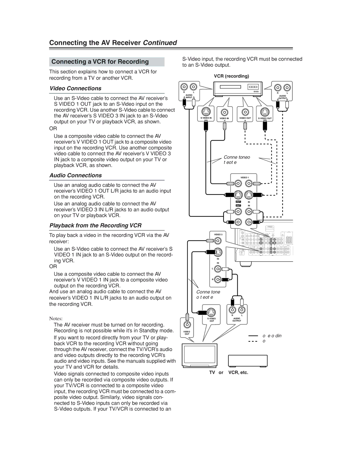
VCR recording
Connecting a VCR for Recording
Playback from the Recording VCR
TV or VCR, etc
Using Optical or Coaxial Connections
PRSatellite, cable, set-top box, LD player, etc
Satellite, cable, set-top box, LD player, etc
Connecting a Camcorder, Game Console, etc
Camcorder Game console, etc
Connecting a CD Player Connecting a Cassette Recorder
Connecting a DAT, CD, or MD Recorder
Using Optical or Coaxial Connections playback only
Digital Recording
Digital source DAT, CD, MD player
Turntable with a Built-in Phono Preamp
Connecting a Turntable
Turntable with an MC Moving Coil Cartridge
Turntable without a Built-in Phono Preamp
On with the AV receiver’s remote controller, as follows
Connecting Components
Connecting the Power Cord of Another Component
When you start playback on an AV component con
Standby indicator
Plug the power cord into an AC wall outlet
Standby indicator will light up
Turning On the AV Receiver
First Time Setup
Automatic Speaker Setup
How to Verify the Measurement Results
First Time Setup
Disconnect the speaker setup microphone
Press Enter
Not Detect
Distance Error
Menus vary depending on country
Tip
About the Onscreen Setup Menus
Submenus Main menu
Initial Setup
Digital Input
Component Video Setup
Config, and then press Enter
Speaker Setup
Buttons to select 1. Speaker
Then use the Left and Right
Buttons to select f. SurrBack
Crossover
Buttons to select d. Surround
Ch, and then use the Left
Buttons to select h. Double
Setup menu closes
Double Bass
Bass, and then use the Left
Speaker Distance
Repeat for all speakers Press the Setup button
Setup menu closes
Buttons to specify the dis- tance
Speaker Level Calibration
Equalizer Setting
Changing the Input Display
Video 3 ↔ HDD
Source
Basic Operations
Selecting the Input Source
Receiver button, and then use the Input Selector buttons
Using Headphones
Setting the Display Brightness
Using the Sleep Timer
Basic Operations
Channel information, this will be
Displaying Source Information
Left and surround right. If there’s surround back
Interpreting Surround Channel Values
Listening to the Radio
Using the Tuner
Tuning into Radio Stations
Displaying Radio Information
Connecting the XM Antenna
Listening to XM Satellite Radio
Signing Up for XM Satellite Radio
Selecting XM Radio Channels
Buttons to select a chan
Displaying XM Radio Information
Selecting XM Channels from the Front Panel
Nel
XM Radio Messages
Positioning the XM Antenna
Presetting AM/FM Stations & XM Channels
Selecting Presets
Deleting Presets
Selecting with the Remote Controller
Selecting Listening Modes
Selecting on the AV receiver
Multich
About the Listening Modes
Onkyo Original DSP Modes
Using the Late Night Function Dolby Digital only
Using the CinemaFILTER
Advanced Operations
Advanced Operations
Using the DVD Analog Multichannel
Adjusting Individual Speaker Levels
Input
Adjusting Individual Speaker Levels
Recording
DVD Video 1 Video 2 select the AV component that
AV Recording Recording Separate AV Sources
Use the input selector buttons to
You want to record
Advanced Setup
Adjusting the Bass & Treble
Audio Adjust Functions
PL IIx Music Mode Settings
Advanced Setup
Input Channel Settings
Neo6 Music Mode Setting
Assigning Listening Modes to Input Sources
Input Setup menu appears
Use the Up and Down Buttons to select the signal for
Buttons to select 7. Input
IntelliVolume
IntelliVolume
Setting Preferences
Then press Enter
Digital Input Signal Formats
InterlacedDefault
Non-InterlacedSelect if the text flickers
Changing the Remote Controller’s ID
You can enter 1, 2, or
Using Only Speakers in Zone
Connecting Zone
Using a Receiver/Integrated Amp in Zone
Zone
Setting the Powered Zone
Buttons to select f. Powered
Zone 2, and use the Left
AV receiver and press
Using Zone
To adjust the Zone 2 volume with
Zone 2 button followed by the on button
Using a Multiroom Kit with a Cabinet
Using the Remote Control in Zone
Using the 12V Trigger
Using a Multiroom Kit with Zone
Entering Remote Control Codes
Controlling Other Components
Set, press the Standby button
Resetting the Remote Mode Buttons
Resetting the Remote Controller
Remote Control Codes for Onkyo Components Connected via
Controlling Other Components
CH +
CH +/-, TV CH +
TV VOL
REC
Following buttons cannot learn new commands
Learning Commands from Other Remote Controllers
Mode button for the mode
Which you want to use the com
Running Macros
Using Macros
Making Macros
Deleting Macros
Video Section
Specifications
Amplifier Section
Tuner Section
Troubleshooting
Troubleshooting
Can’t control other components?
Remote controller doesn’t work?
Can’t select XM radio channels
Can’t record?
Speaker distance cannot be set as required?
Sound changes when I connect my head- phones?
Speaker volume cannot be set as required?
Display doesn’t work?
3 4 4 0 9
Page
Page
Page
Page
Page
Page
Page
Page
Page
Page
Page
Page
Page