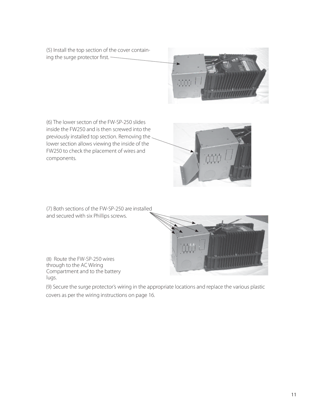
(5)Install the top section of the cover contain- ing the surge protector fi rst.

(6)The lower secton of the FW-SP-250 slides inside the FW250 and is then screwed into the previously installed top section. Removing the lower section allows viewing the inside of the

FW250 to check the placement of wires and components.

(7) Both sections of the FW-SP-250 are installed and secured with six Phillips screws.

(8)Route the FW-SP-250 wires through to the AC Wiring Compartment and to the battery lugs.

(9)Secure the surge protector’s wiring in the appropriate locations and replace the various plastic covers as per the wiring instructions on page 16.

11

Page 12
Image 12
Outback Power Systems FW-SP-250, FW-SP-ACA, FW-SP-R manual FW250 to check the placement of wires and components