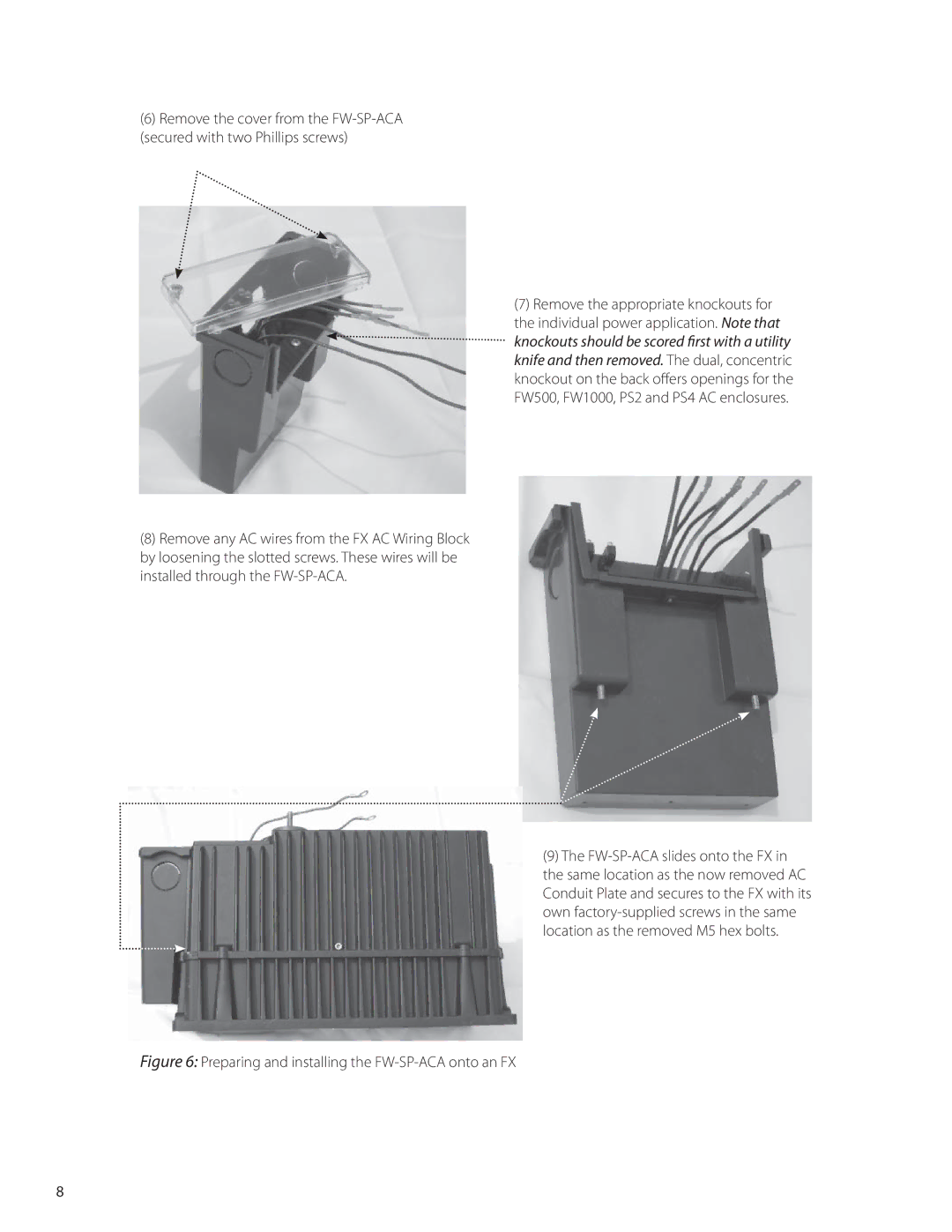
(6)Remove the cover from the
(8)Remove any AC wires from the FX AC Wiring Block by loosening the slotted screws. These wires will be installed through the
(7)Remove the appropriate knockouts for the individual power application. Note that knockouts should be scored first with a utility knife and then removed. The dual, concentric knockout on the back offers openings for the FW500, FW1000, PS2 and PS4 AC enclosures.
(9)The FW-SP-ACA slides onto the FX in
the same location as the now removed AC Conduit Plate and secures to the FX with its own
Figure 6: Preparing and installing the FW-SP-ACA onto an FX
8