Electrical Connections and LED Indicators
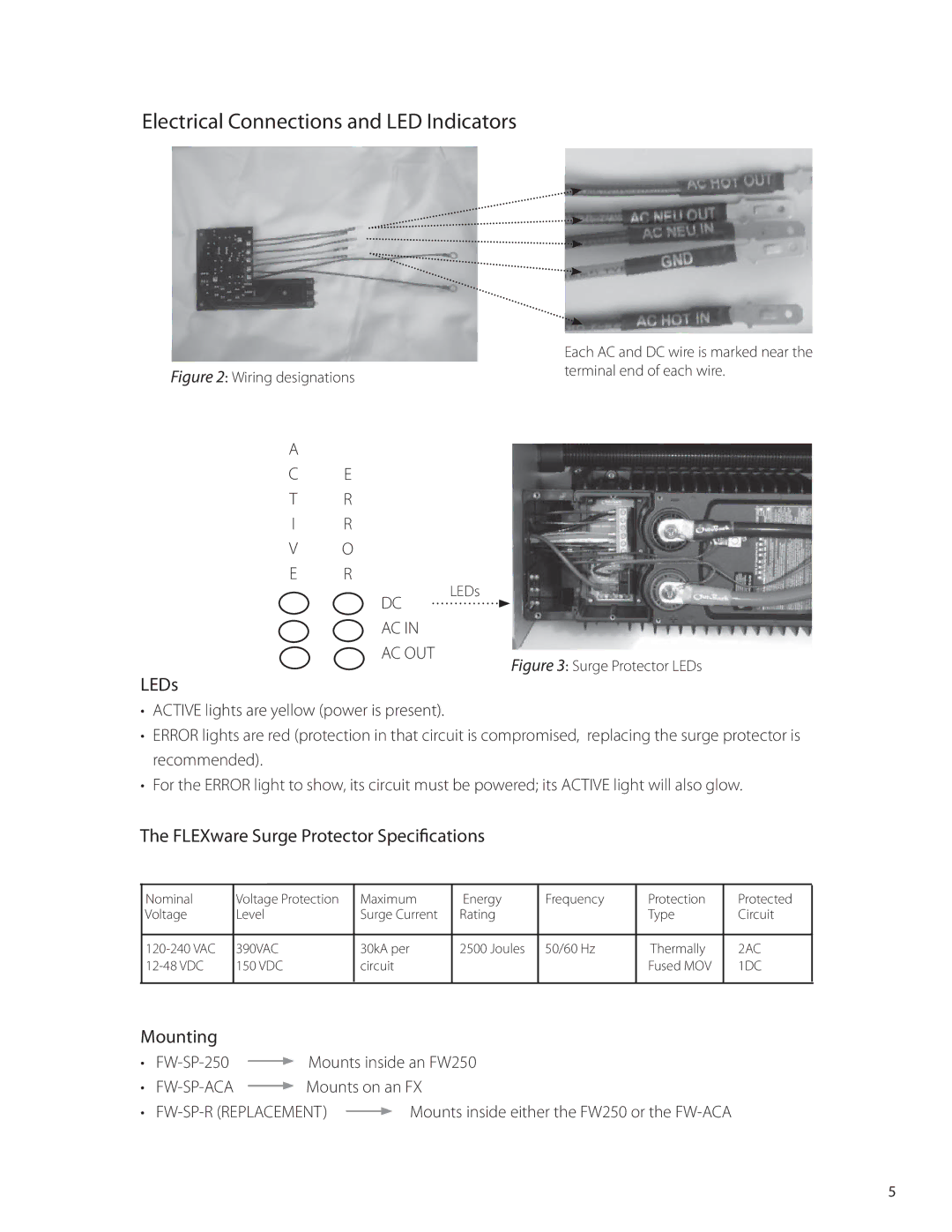
| Each AC and DC wire is marked near the |
Figure 2: Wiring designations | terminal end of each wire. |
|
A
CE
TR
IR
VO
E R
LEDs
DC
AC IN
AC OUT
Figure 3: Surge Protector LEDs
LEDs
•ACTIVE lights are yellow (power is present).
•ERROR lights are red (protection in that circuit is compromised, replacing the surge protector is recommended).
•For the ERROR light to show, its circuit must be powered; its ACTIVE light will also glow.
The FLEXware Surge Protector Specifications
Nominal | Voltage Protection | Maximum | Energy | Frequency | Protection | Protected |
Voltage | Level | Surge Current | Rating |
| Type | Circuit |
390VAC | 30kA per | 2500 Joules | 50/60 Hz | Thermally | 2AC | |
150 VDC | circuit |
|
| Fused MOV | 1DC | |
|
|
|
|
|
|
|
Mounting
• |
| Mounts inside an FW250 | |||
| |||||
• |
| Mounts on an FX | |||
| |||||
• |
| Mounts inside either the FW250 or the | |||
| |||||
5
