| M |
ON | POWER |
OFF |
|
METER |
|
FULL/FINE |
|
L |
|
MONITOR SELECT |
|
R |
|
| MONITOR |
HEADPHONES | MIX |
DVCPRO
DV
A VOL | INPUT SELECT | PREVIEW/PREVIEW AUTO EDIT PREROLL |
SELECT |
|
|
DVCPRO 50
COUNTER ASSEM | VIDEO | CUE | TC | STAND BY | PLAYER | RECORDER | JOG | SHTL | SLOW |
RESET CH1 | CH2 | CH3 | CH4 |
|
|
|
|
|
|
|
|
|
| EDIT | PLAY | REC |
|
|
|
A IN | INSERT | A OUT |
|
|
|
|
|
| |
|
|
|
|
|
|
|
| ||
| TRIM |
|
|
|
|
|
|
|
|
| SET |
|
| REW | STOP | FF |
|
|
|
|
|
|
|
|
|
|
|
| |
IN |
| OUT |
|
|
|
|
|
|
|
PA VOL SELECT button and lamps |
(REC LEVEL, PB LEVEL) |
This switches the function of the audio level control |
knobs Q between recording and playback. |
Each time this button is pressed (for 1 second or |
longer), the functioning of the audio level control |
knobs switches alternately been recording and |
playback. |
VIDEO AUDIO
CH1 | CH2 | CH3 | CH4 | TC | SUPER | REC INH | INT TCG | MODE | CONTROL |
REC LEVEL |
|
| UNITY | PRESET MENU SET | DIAG ON | ON | REGEN | TAPE | REMOTE |
|
|
|
|
|
| PRESET |
|
| |
PB LEVEL |
|
| VAR |
| OFF | OFF | EXIT | EE | LOCAL |
ONP Q RS
T
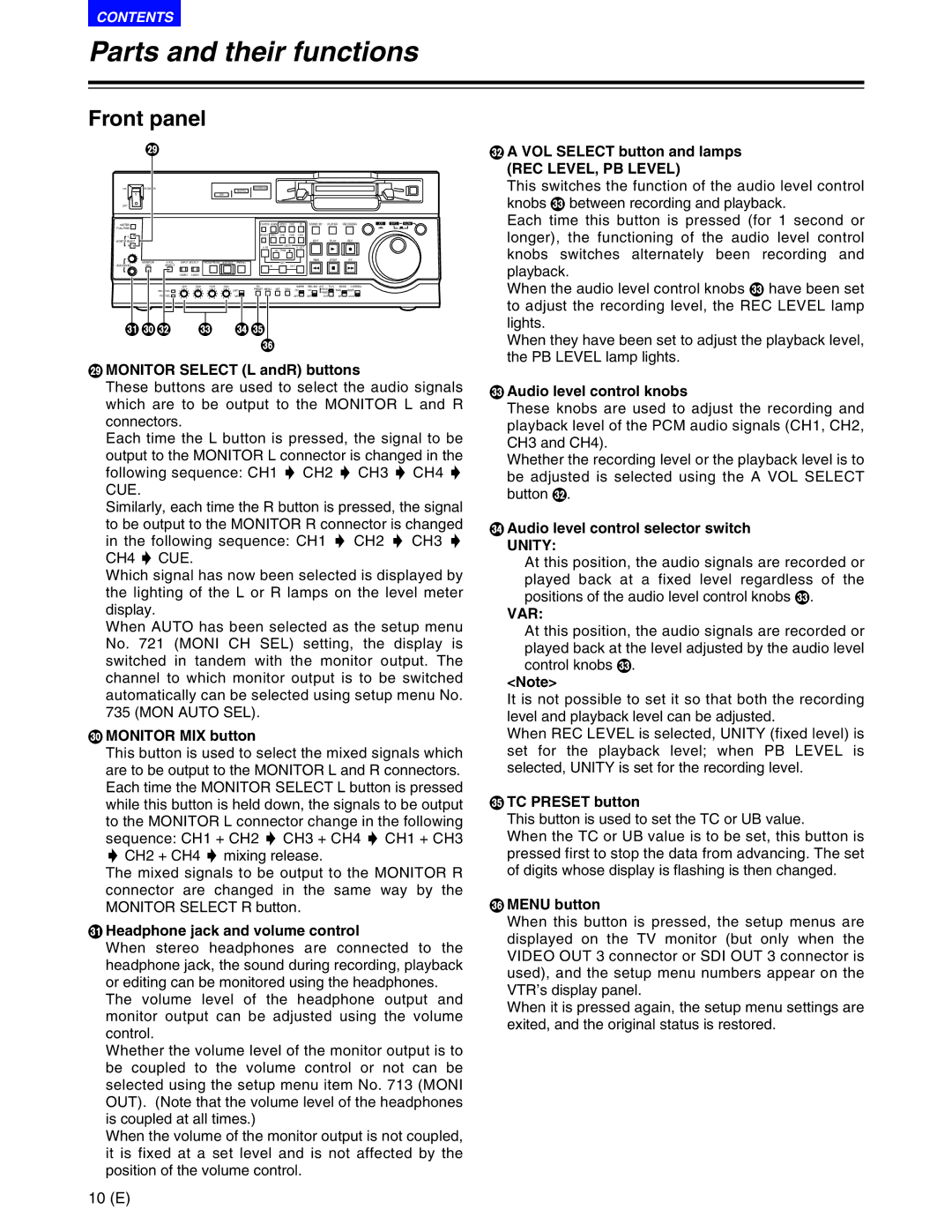
MMONITOR SELECT (L andR) buttons
These buttons are used to select the audio signals which are to be output to the MONITOR L and R connectors.
Each time the L button is pressed, the signal to be output to the MONITOR L connector is changed in the following sequence: CH1 5 CH2 5 CH3 5 CH4 5 CUE.
Similarly, each time the R button is pressed, the signal to be output to the MONITOR R connector is changed in the following sequence: CH1 5 CH2 5 CH3 5 CH4 5 CUE.
Which signal has now been selected is displayed by the lighting of the L or R lamps on the level meter display.
When AUTO has been selected as the setup menu No. 721 (MONI CH SEL) setting, the display is switched in tandem with the monitor output. The channel to which monitor output is to be switched automatically can be selected using setup menu No. 735 (MON AUTO SEL).
NMONITOR MIX button
This button is used to select the mixed signals which are to be output to the MONITOR L and R connectors. Each time the MONITOR SELECT L button is pressed while this button is held down, the signals to be output to the MONITOR L connector change in the following sequence: CH1 + CH2 5 CH3 + CH4 5 CH1 + CH3 5 CH2 + CH4 5 mixing release.
The mixed signals to be output to the MONITOR R connector are changed in the same way by the MONITOR SELECT R button.
OHeadphone jack and volume control
When stereo headphones are connected to the headphone jack, the sound during recording, playback or editing can be monitored using the headphones.
The volume level of the headphone output and monitor output can be adjusted using the volume control.
Whether the volume level of the monitor output is to be coupled to the volume control or not can be selected using the setup menu item No. 713 (MONI OUT). (Note that the volume level of the headphones is coupled at all times.)
When the volume of the monitor output is not coupled, it is fixed at a set level and is not affected by the position of the volume control.
When the audio level control knobs Q have been set |
to adjust the recording level, the REC LEVEL lamp |
lights. |
When they have been set to adjust the playback level, |
the PB LEVEL lamp lights. |
QAudio level control knobs
These knobs are used to adjust the recording and playback level of the PCM audio signals (CH1, CH2, CH3 and CH4).
Whether the recording level or the playback level is to be adjusted is selected using the A VOL SELECT button P.
RAudio level control selector switch
UNITY:
At this position, the audio signals are recorded or played back at a fixed level regardless of the positions of the audio level control knobs Q.
VAR:
At this position, the audio signals are recorded or played back at the level adjusted by the audio level control knobs Q.
<Note>
It is not possible to set it so that both the recording level and playback level can be adjusted.
When REC LEVEL is selected, UNITY (fixed level) is set for the playback level; when PB LEVEL is selected, UNITY is set for the recording level.
STC PRESET button
This button is used to set the TC or UB value.
When the TC or UB value is to be set, this button is pressed first to stop the data from advancing. The set of digits whose display is flashing is then changed.
TMENU button
When this button is pressed, the setup menus are displayed on the TV monitor (but only when the VIDEO OUT 3 connector or SDI OUT 3 connector is used), and the setup menu numbers appear on the VTR’s display panel.
When it is pressed again, the setup menu settings are exited, and the original status is restored.
10 (E)