CONTENTS
SDTI interface
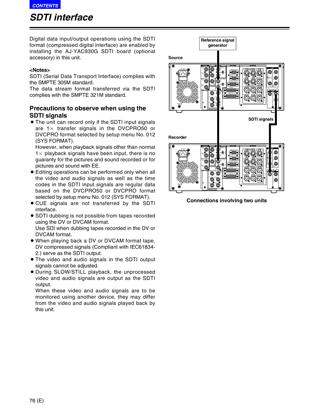
Digital data input/output operations using the SDTI format (compressed digital interface) are enabled by installing the
<Notes>
SDTI (Serial Data Transport Interface) complies with the SMPTE 305M standard.
The data stream format transferred via the SDTI complies with the SMPTE 321M standard.
Precautions to observe when using the SDTI signals
O The unit can record only if the SDTI input signals are 1a transfer signals in the DVCPRO50 or DVCPRO format selected by setup menu No. 012
Source
![]() AC IN
AC IN
SIGNAL
GND
Reference signal
generator
AES/EBU |
|
|
| REMOTE |
| ANALOG |
|
|
|
| ||
CH1/2 |
|
| VIDEO |
|
|
|
|
|
|
|
| SDI |
IN |
|
| IN |
|
|
|
|
|
|
|
| |
|
|
| ON | REMOTE IN/OUT | CH1 PUSH AUDIO PUSH CH2 | PUSH | TC | IN | OUT | |||
|
|
|
|
|
|
| IN |
|
| IN |
|
|
CH3/4 | Y |
| 75Ω |
|
|
|
|
|
|
|
|
|
IN |
|
| OFF |
|
|
|
|
|
|
|
| 1 |
|
|
|
| REMOTE | OUT |
|
|
|
|
|
|
|
| PB |
|
|
|
| CH3 PUSH |
| PUSH CH4 |
| TC |
| ACTIVE |
|
|
|
|
|
|
| THROUGH | |||||
CH1/2 |
|
| REF VIDEO |
|
|
|
|
|
| OUT |
| 2 |
OUT |
|
| IN |
|
|
|
|
|
|
|
| |
|
|
| ON | ENCODER REMOTE |
|
|
|
|
|
|
| |
|
|
|
|
|
|
|
|
|
|
|
| |
CH3/4 | PR |
| 75Ω |
|
|
|
|
|
|
|
| 3 |
OUT | OPTION |
| OFF |
|
| CH1 | AUDIO | CH2 |
| MON |
| (SUPER) |
|
|
|
|
|
| OUT |
|
| L |
|
| |
|
|
|
|
|
|
|
|
|
|
|
| OPTION |
| Y | 1 | VIDEO |
|
|
|
|
|
|
|
| SDTI |
|
|
| OUT | PARALLEL |
|
|
|
|
|
| IN | OUT |
|
|
|
|
|
|
|
|
| MON |
|
| |
|
|
|
|
|
| CH3 |
| CH4 |
|
| 1 | |
| PB | 2 |
|
|
|
|
|
|
| R |
| |
| (WFM) |
|
|
|
|
|
|
|
|
|
| |
|
| 3 |
|
|
|
|
|
|
|
|
| 2 |
| PR |
|
|
|
|
|
|
|
|
|
| |
|
|
|
|
|
|
|
|
|
|
|
| |
| SERVICE ONLY |
|
|
|
|
|
|
|
|
|
| |
SDTI signals
(SYS FORMAT).
However, when playback signals other than normal 1a playback signals have been input, there is no guaranty for the pictures and sound recorded or for pictures and sound with EE.
O Editing operations can be performed only when all the video and audio signals as well as the time codes in the SDTI input signals are regular data based on the DVCPRO50 or DVCPRO format selected by setup menu No. 012 (SYS FORMAT).
Recorder
![]() AC IN
AC IN
SIGNAL
GND
AES/EBU |
|
|
| REMOTE |
| ANALOG |
|
|
|
| ||
CH1/2 |
|
| VIDEO |
|
|
|
|
|
|
|
| SDI |
IN |
|
| IN |
|
|
|
|
|
|
| IN | |
|
|
| ON | REMOTE IN/OUT | CH1 PUSH AUDIO PUSH CH2 | PUSH | TC | OUT | ||||
|
|
|
|
|
|
| IN |
|
| IN |
|
|
CH3/4 | Y |
| 75Ω |
|
|
|
|
|
|
|
|
|
|
|
|
|
|
|
|
|
|
|
| 1 | |
IN |
|
| OFF |
|
|
|
|
|
|
|
| |
|
|
|
| REMOTE | OUT |
|
|
|
|
|
|
|
| PB |
|
|
|
| CH3 PUSH |
| PUSH CH4 |
| TC |
|
|
CH1/2 |
|
| REF VIDEO |
|
|
|
|
|
| OUT |
| 2 |
OUT |
|
| IN |
|
|
|
|
|
|
|
| |
|
|
| ON | ENCODER REMOTE |
|
|
|
|
|
|
| |
|
|
|
|
|
|
|
|
|
|
|
| |
CH3/4 | PR |
| 75Ω |
|
|
|
|
|
|
|
| 3 |
OPTION |
|
|
|
|
|
|
|
|
|
| ||
OUT |
| OFF |
|
| CH1 | AUDIO | CH2 |
| MON |
| (SUPER) | |
|
|
|
|
|
| OUT |
|
| L |
|
| |
Y |
| 1 | VIDEO |
|
|
|
|
|
|
|
| SDTI |
|
|
| OUT | PARALLEL |
|
|
|
|
|
| IN | OUT |
|
|
|
|
|
|
|
|
| MON |
|
| |
|
|
|
|
|
| CH3 |
| CH4 |
|
| 1 | |
PB |
| 2 |
|
|
|
|
|
|
| R |
| |
| (WFM) |
|
|
|
|
|
|
|
|
|
| |
|
| 3 |
|
|
|
|
|
|
|
|
| 2 |
PR |
|
|
|
|
|
|
|
|
|
|
| |
(SUPER) |
|
|
|
|
|
|
|
|
|
| ||
SERVICE ONLY |
|
|
|
|
|
|
|
|
|
| ||
O CUE signals are not transferred by the SDTI interface.
O SDTI dubbing is not possible from tapes recorded using the DV or DVCAM format.
Use SDI when dubbing tapes recorded in the DV or DVCAM format.
O When playing back a DV or DVCAM format tape, DV compressed signals (Compliant with IEC61834- 2.) serve as the SDTI output.
O The video and audio signals in the SDTI output signals cannot be adjusted.
O During SLOW/STILL playback, the unprocessed video and audio signals are output as the SDTI output.
When these video and audio signals are to be monitored using another device, they may differ from the video and audio signals played back by this unit.
Connections involving two units
76 (E)