
PT-L750U R, TQBH9003-6 specifications
The Panasonic TQBH9003-6, PT-L750U R is a remarkable projector designed for versatile professional use, ideal for a wide range of applications from corporate presentations to educational settings. This high-performance model combines cutting-edge technology with user-friendly features to deliver stunning visuals and reliable operation.One of the standout characteristics of the PT-L750U R is its brightness, boasting an impressive output of 7,500 lumens. This high brightness level ensures vivid and sharp images even in well-lit environments, making it perfect for large conference rooms or lecture halls. Coupled with a high contrast ratio, the projector produces deep blacks and vibrant colors, enhancing the overall viewing experience.
The projector employs advanced DLP technology, renowned for its excellent color accuracy and longevity. This technology minimizes the risk of color degradation over time, ensuring that images remain consistent in quality throughout its lifespan. The inclusion of a durable laser light source not only increases the projector's longevity but also enhances its energy efficiency, significantly reducing maintenance costs.
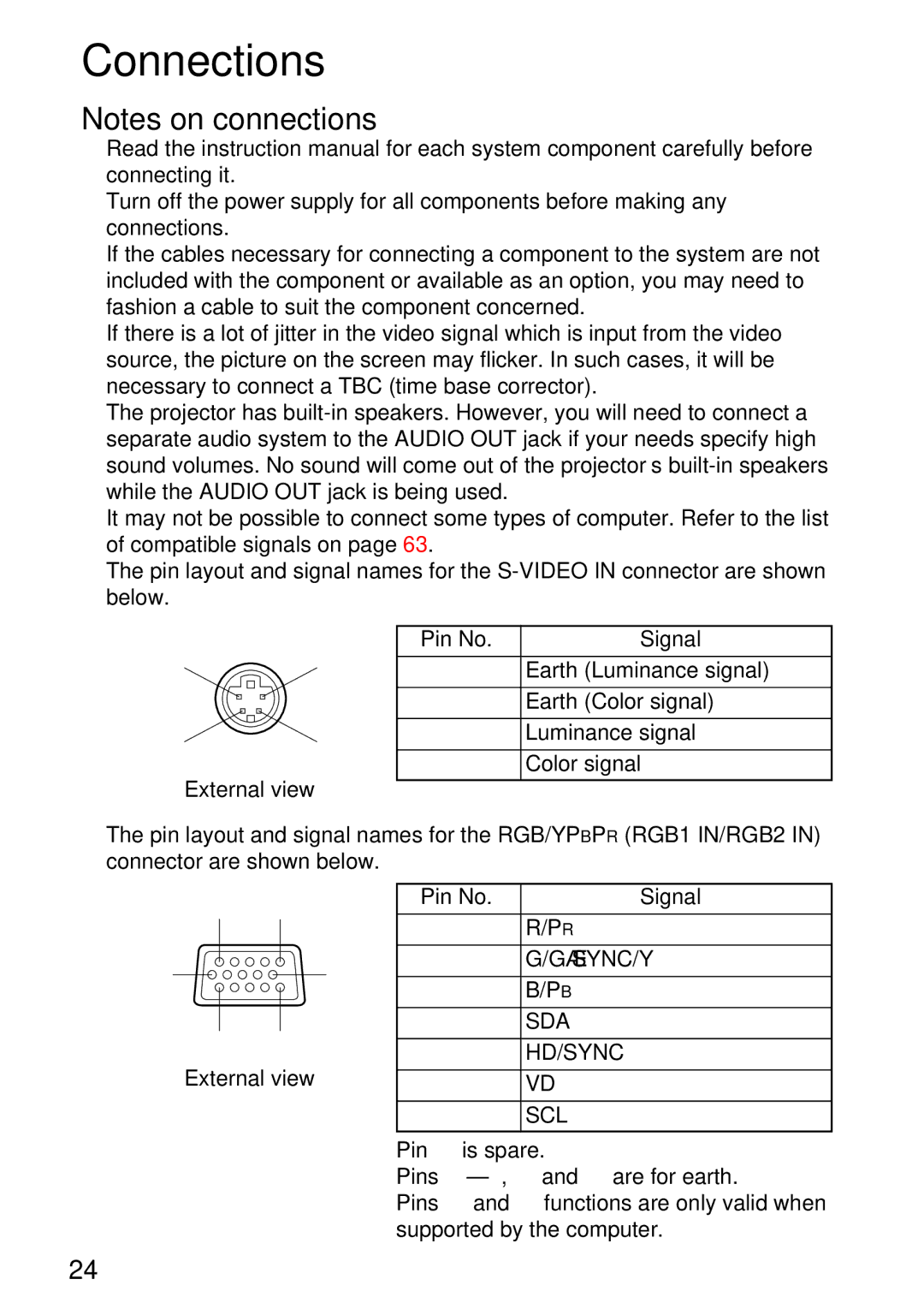
Connectivity is another critical feature of the Panasonic PT-L750U R. It comes equipped with a range of input options, including HDMI, USB, and LAN, allowing for easy integration with various devices. This flexibility makes it suitable for different content sources, whether it be streaming media, laptops, or presentation tools. The projector also supports wireless connectivity, enabling users to present content directly from their smartphones or tablets without cumbersome cables.
In terms of design, the PT-L750U R is compact and lightweight, making it easy to transport and install in various environments. The projector is also equipped with advanced lens shift and keystone correction capabilities, allowing for easy adjustments to achieve the perfect image alignment, despite the placement of the device.
Furthermore, the Panasonic TQBH9003-6 model emphasizes quiet operation, ensuring that fan noise is minimized, allowing for undistracted presentations. This feature is particularly beneficial in settings where concentration and focus are essential.
In conclusion, the Panasonic TQBH9003-6, PT-L750U R is a powerful, versatile projector that delivers high-quality visuals with a range of advanced features to cater to the demands of professional settings. Its combination of brightness, connectivity options, and user-friendly design makes it a top choice for anyone seeking reliable projection solutions in corporate or educational environments.