Installations/Connections
Before start the installation/connection, prepare the required devices and cables.
Before starting the connection, turn the power of the devices including the camera and the PC off or disconnect the AC adapters from the outlet.
Step 1
Fix an optional camera mount base onto the desired place and mount the camera on it. When attaching an optional camera mount base on the bottom of the camera, use the removed screws to attach the camera mount base.
Otherwise, it may cause a drop or malfunc- tion.
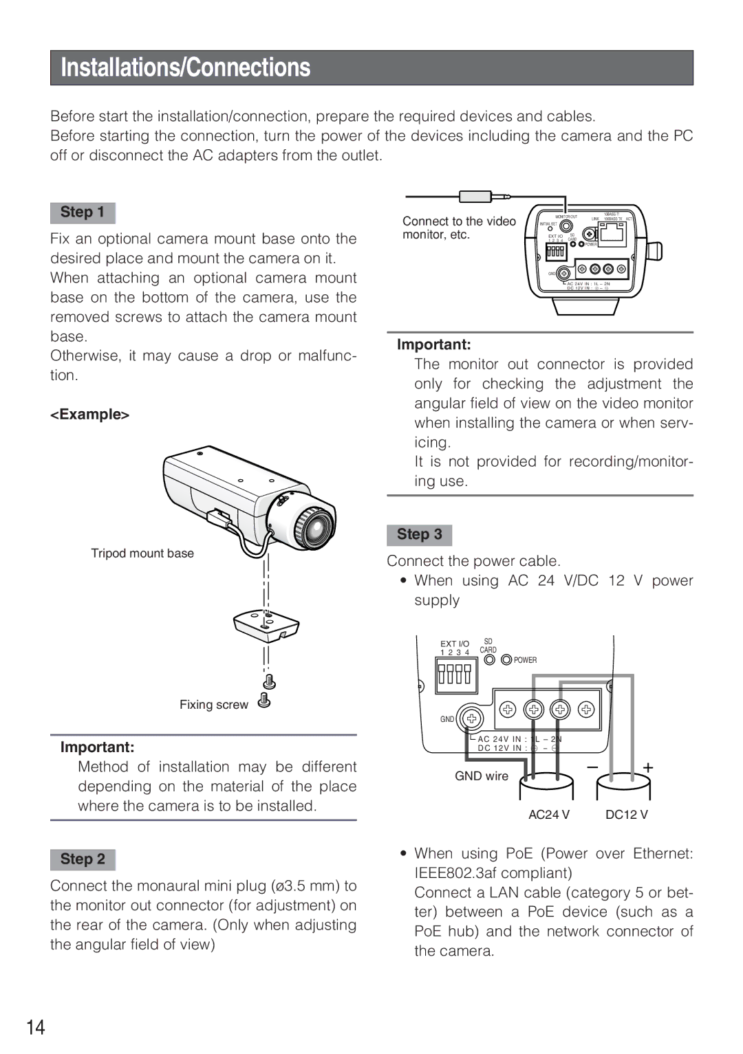
<Example>
Tripod mount base
Connect to the video | MONITOR OUT | ||
LINK | |||
INITIAL SET |
|
| |
monitor, etc. | 1 2 3 4 | CARD |
|
| EXT I/O | SD |
|
POWER
GND
![]() AC 24V IN : 1L – 2N
AC 24V IN : 1L – 2N
DC 12V IN : ! – @
Important:
The monitor out connector is provided only for checking the adjustment the angular field of view on the video monitor when installing the camera or when serv- icing.
It is not provided for recording/monitor- ing use.
Step 3
Connect the power cable.
•When using AC 24 V/DC 12 V power supply
EXT I/O | SD | ||
1 2 | 3 | 4 | CARD |
POWER
Fixing screw
Important:
Method of installation may be different depending on the material of the place where the camera is to be installed.
Step 2
Connect the monaural mini plug (ø3.5 mm) to the monitor out connector (for adjustment) on the rear of the camera. (Only when adjusting the angular field of view)
GND
![]() AC 24V IN : 1L – 2N
AC 24V IN : 1L – 2N
DC 12V IN : ! – @
GND wire | – | + |
|
| |
| AC24 V | DC12 V |
•When using PoE (Power over Ethernet: IEEE802.3af compliant)
Connect a LAN cable (category 5 or bet- ter) between a PoE device (such as a PoE hub) and the network connector of the camera.
14