FIGURE 7 |
| |
| 11 3/8 X | |
| Y | |
| 28 | |
| D | |
AI | X | |
SECURELY 37 | ||
| ||
TIGHTEN! |
| |
| E | |
3/8 X |
|
STEP 7:
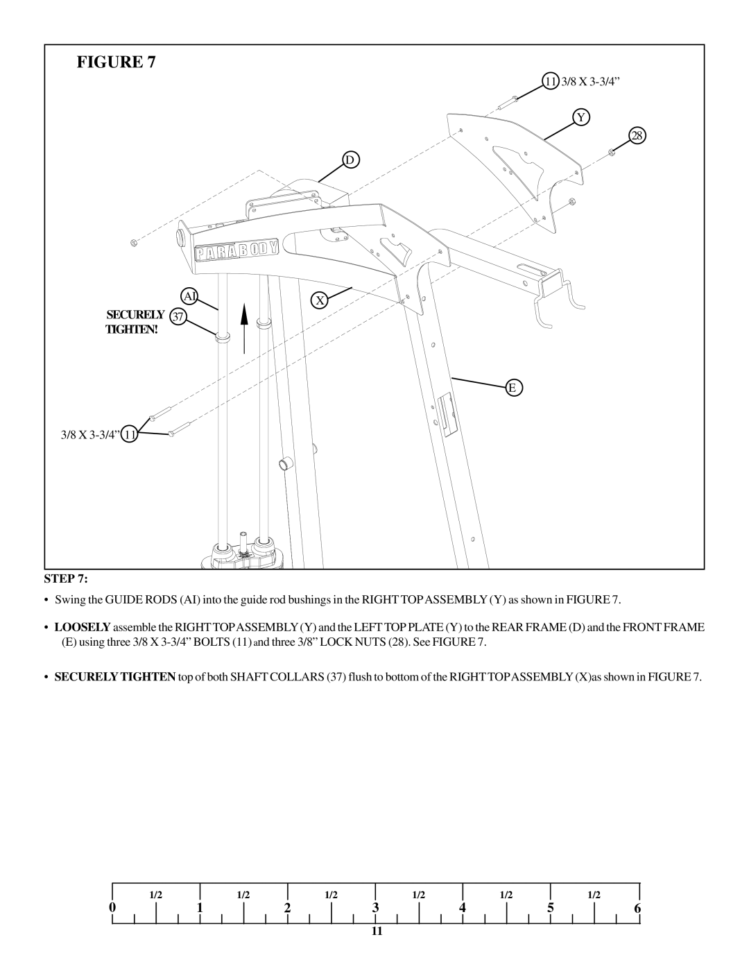
•Swing the GUIDE RODS (AI) into the guide rod bushings in the RIGHT TOPASSEMBLY (Y) as shown in FIGURE 7.
•LOOSELY assemble the RIGHT TOPASSEMBLY (Y) and the LEFT TOP PLATE (Y) to the REAR FRAME (D) and the FRONT FRAME
(E)using three 3/8 X
•SECURELYTIGHTEN top of both SHAFT COLLARS (37) flush to bottom of the RIGHT TOPASSEMBLY (X)as shown in FIGURE 7.
| 1/2 |
| 1/2 |
| 1/2 |
| 1/2 |
| 1/2 |
|
| 1/2 |
0 | 1 | 2 | 3 | 4 | 5 | 6 | ||||||
11
