| I |
| Q |
AO | 27 |
R |
|
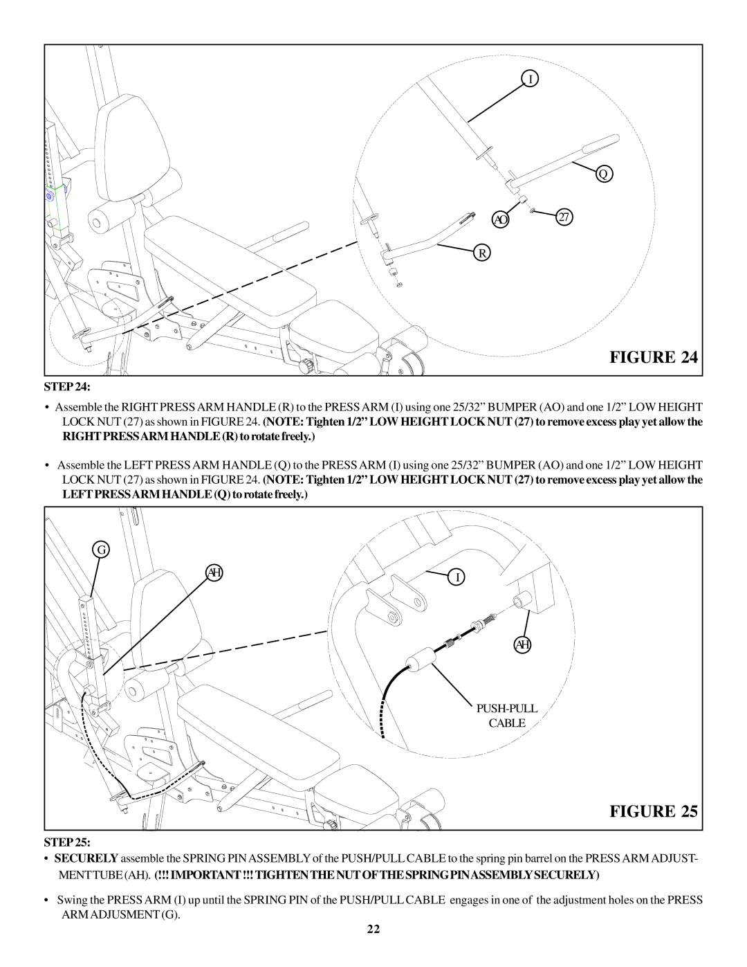
| FIGURE 24 |
STEP 24:
•Assemble the RIGHT PRESS ARM HANDLE (R) to the PRESS ARM (I) using one 25/32” BUMPER (AO) and one 1/2” LOW HEIGHT LOCK NUT (27) as shown in FIGURE 24. (NOTE: Tighten 1/2” LOW HEIGHT LOCK NUT (27) to remove excess play yet allow the
RIGHTPRESSARM HANDLE (R) to rotate freely.)
•Assemble the LEFT PRESS ARM HANDLE (Q) to the PRESS ARM (I) using one 25/32” BUMPER (AO) and one 1/2” LOW HEIGHT LOCK NUT (27) as shown in FIGURE 24. (NOTE: Tighten 1/2” LOW HEIGHT LOCK NUT (27) to remove excess play yet allow the
LEFTPRESSARM HANDLE (Q) to rotate freely.)
G |
|
AH | I |
| |
| AH |
| |
| CABLE |
| FIGURE 25 |
STEP 25:
•SECURELY assemble the SPRING PINASSEMBLY of the PUSH/PULL CABLE to the spring pin barrel on the PRESS ARM ADJUST-
MENTTUBE (AH). (!!!IMPORTANT!!!TIGHTENTHENUTOFTHESPRINGPINASSEMBLYSECURELY)
•Swing the PRESS ARM (I) up until the SPRING PIN of the PUSH/PULL CABLE engages in one of the adjustment holes on the PRESS ARMADJUSMENT (G).
22
