49 | AA | (b) |
|
|
|
|
| ||
| X | Z | (d) |
|
28 | 50 |
|
| |
| 30 |
|
| |
|
|
|
| |
|
| Y |
| (e) |
|
| 28 | 49 | |
|
|
| ||
|
|
| 28 | |
|
|
|
| |
3/8 X 2” 16 |
| 3/8 X | 40 | |
|
|
| ||
| X |
| E |
|
|
|
|
| |
28 |
|
|
| 39 |
|
|
|
| |
| 3/8 X |
|
| AV |
| 11 3/8 X |
|
| |
49 | 17 |
| AL | |
|
| |||
|
|
|
| |
L |
|
|
|
|
(c) |
|
|
|
|
(a) | AV |
|
|
|
|
|
|
| |
| AK |
|
|
|
FIGURE 26 |
|
|
|
|
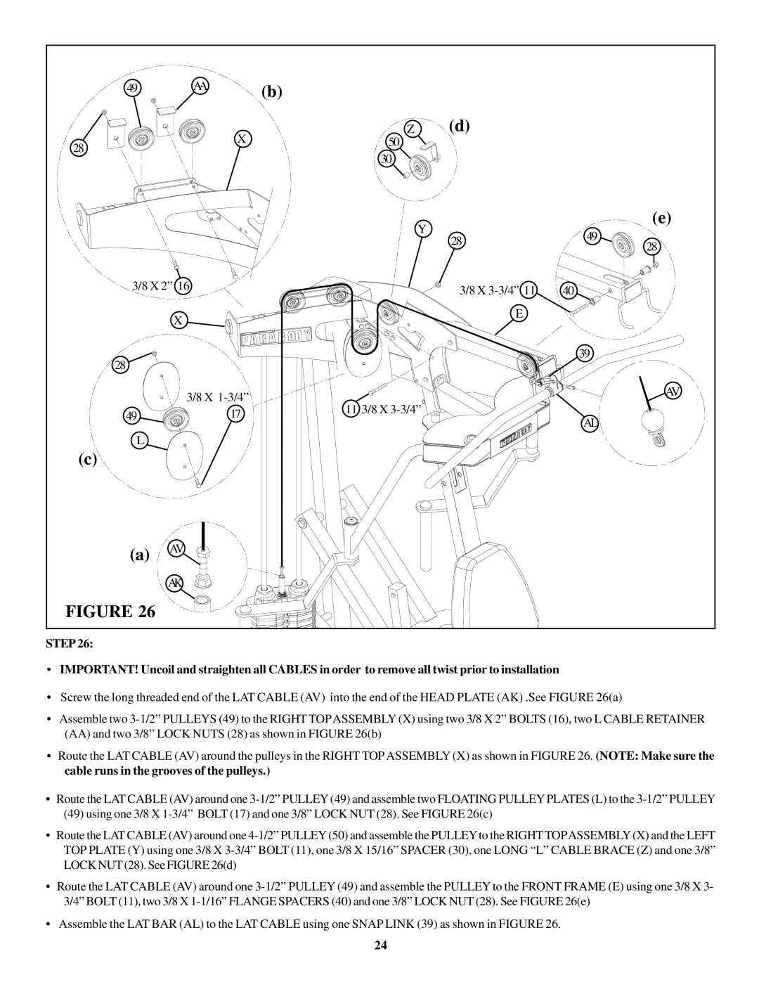
STEP 26:
•IMPORTANT! Uncoil and straighten all CABLES in order to remove all twist prior to installation
•Screw the long threaded end of the LAT CABLE (AV) into the end of the HEAD PLATE (AK) .See FIGURE 26(a)
•Assemble two
•Route the LAT CABLE (AV) around the pulleys in the RIGHT TOPASSEMBLY (X) as shown in FIGURE 26. (NOTE: Make sure the cable runs in the grooves of the pulleys.)
•Route the LAT CABLE (AV) around one
(49)using one 3/8 X
•Route the LAT CABLE (AV) around one
•Route the LAT CABLE (AV) around one
•Assemble the LAT BAR (AL) to the LAT CABLE using one SNAP LINK (39) as shown in FIGURE 26.
24
