15 3/8 X |
23 |
AF |
AG |
28 |
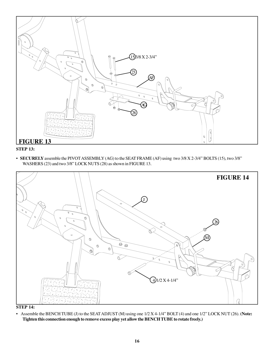
FIGURE 13 |
STEP 13:
•SECURELY assemble the PIVOTASSEMBLY (AG) to the SEAT FRAME (AF) using two 3/8 X
FIGURE 14 |
J |
26 |
M |
4 1/2 X |
STEP 14: |
•Assemble the BENCH TUBE (J) to the SEAT ADJUST (M) using one 1/2 X
Tighten this connection enough to remove excess play yet allow the BENCH TUBE to rotate freely.)
16
