|
| FIGURE 15 |
|
| J |
|
| 27 |
|
| O |
|
| N |
1/2 X 6” | 3 | M |
|
STEP 15:
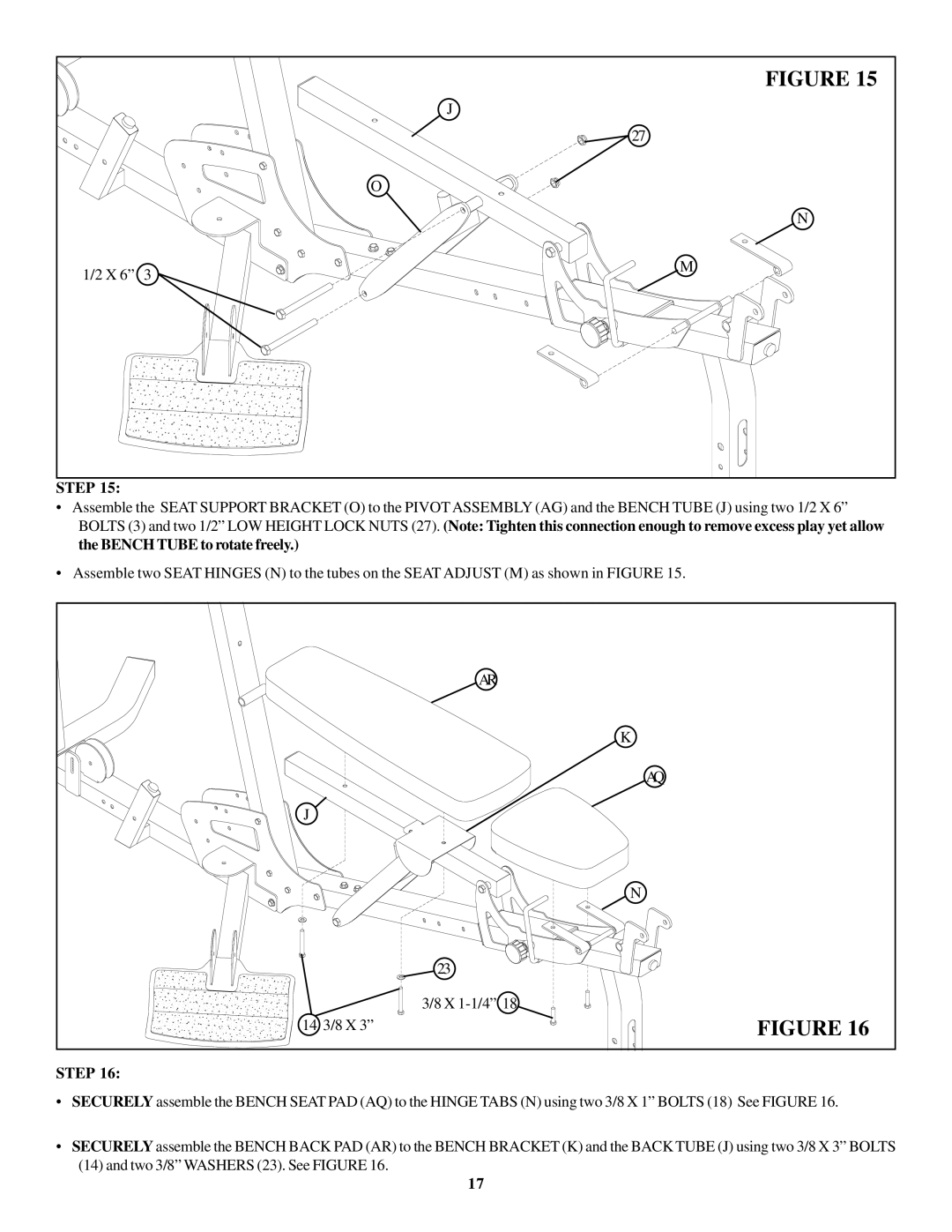
•Assemble the SEAT SUPPORT BRACKET (O) to the PIVOT ASSEMBLY (AG) and the BENCH TUBE (J) using two 1/2 X 6” BOLTS (3) and two 1/2” LOW HEIGHT LOCK NUTS (27). (Note: Tighten this connection enough to remove excess play yet allow the BENCH TUBE to rotate freely.)
•Assemble two SEAT HINGES (N) to the tubes on the SEAT ADJUST (M) as shown in FIGURE 15.
| AR |
| K |
| AQ |
J |
|
| N |
| 23 |
| 3/8 X |
14 3/8 X 3” | FIGURE 16 |
STEP 16:
•SECURELY assemble the BENCH SEAT PAD (AQ) to the HINGE TABS (N) using two 3/8 X 1” BOLTS (18) See FIGURE 16.
•SECURELY assemble the BENCH BACK PAD (AR) to the BENCH BRACKET (K) and the BACK TUBE (J) using two 3/8 X 3” BOLTS
(14)and two 3/8” WASHERS (23). See FIGURE 16.
17
