D
3/8 X
23
28 | A |
|
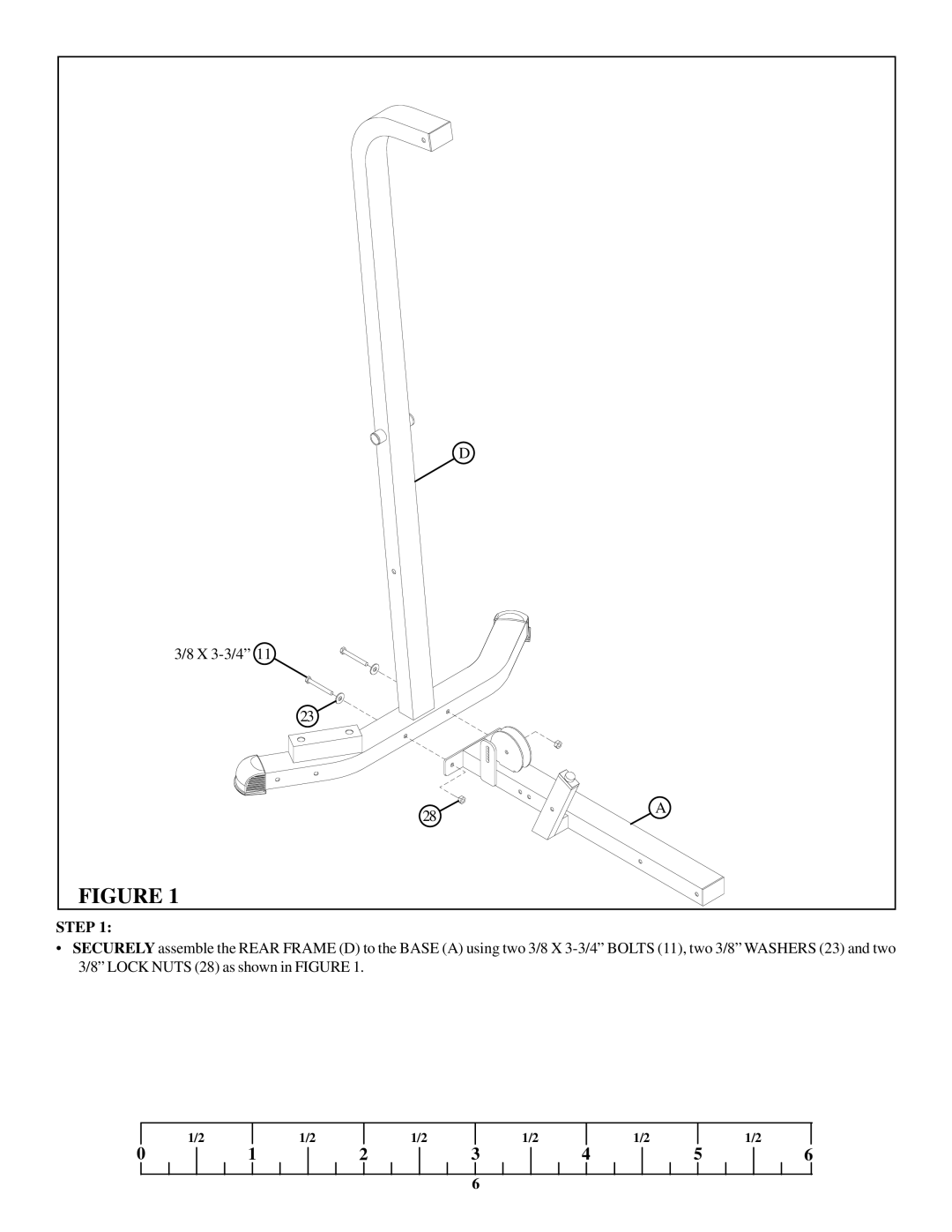
FIGURE 1
STEP 1:
•SECURELY assemble the REAR FRAME (D) to the BASE (A) using two 3/8 X
| 1/2 |
| 1/2 |
| 1/2 |
| 1/2 |
| 1/2 |
|
| 1/2 |
0 | 1 | 2 | 3 | 4 | 5 | 6 | ||||||
6
D
3/8 X
23
28 | A |
|
FIGURE 1
•SECURELY assemble the REAR FRAME (D) to the BASE (A) using two 3/8 X
| 1/2 |
| 1/2 |
| 1/2 |
| 1/2 |
| 1/2 |
|
| 1/2 |
0 | 1 | 2 | 3 | 4 | 5 | 6 | ||||||
6