(b) | | FIGURE 30 |
E | 28 | |
| |
49 | | |
C | | |
3/8 X 5-3/4” 9 | AX | |
| |
| | 15 3/8 X 2-3/4” |
| S | C |
| 49 |
| |
| | U |
| | T |
| | (a) |
| | 28 |
| | 50 |
| | 28 |
| | W |
| | 17 3/8 X 1-3/4” |
| | (c) |
STEP 30:
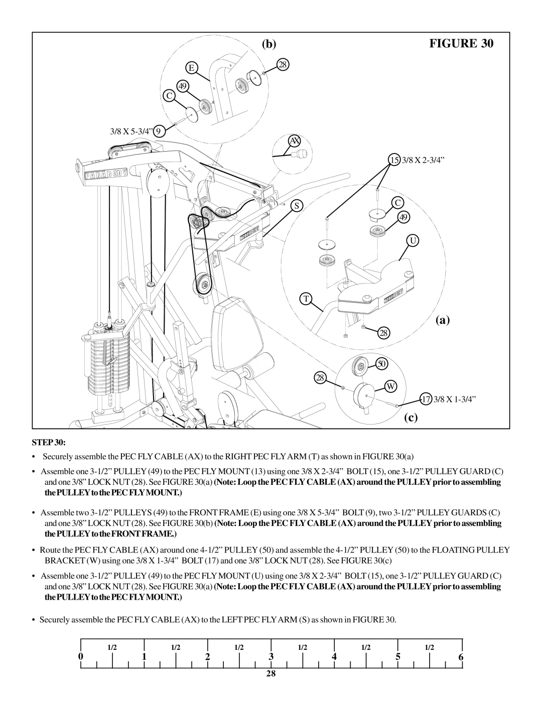
•Securely assemble the PEC FLY CABLE (AX) to the RIGHT PEC FLYARM (T) as shown in FIGURE 30(a)
•Assemble one 3-1/2” PULLEY (49) to the PEC FLY MOUNT (13) using one 3/8 X 2-3/4” BOLT (15), one 3-1/2” PULLEY GUARD (C) and one 3/8” LOCK NUT (28). See FIGURE 30(a) (Note: Loop the PEC FLY CABLE (AX) around the PULLEY prior to assembling thePULLEYtothePECFLYMOUNT.)
•Assemble two 3-1/2” PULLEYS (49) to the FRONT FRAME (E) using one 3/8 X 5-3/4” BOLT (9), two 3-1/2” PULLEY GUARDS (C) and one 3/8” LOCK NUT (28). See FIGURE 30(b) (Note: Loop the PEC FLYCABLE (AX) around the PULLEYprior to assembling thePULLEYtotheFRONTFRAME.)
•Route the PEC FLY CABLE (AX) around one 4-1/2” PULLEY (50) and assemble the 4-1/2” PULLEY (50) to the FLOATING PULLEY BRACKET (W) using one 3/8 X 1-3/4” BOLT (17) and one 3/8” LOCK NUT (28). See FIGURE 30(c)
•Assemble one 3-1/2” PULLEY (49) to the PEC FLY MOUNT (U) using one 3/8 X 2-3/4” BOLT (15), one 3-1/2” PULLEY GUARD (C) and one 3/8” LOCK NUT (28). See FIGURE 30(a) (Note: Loop the PEC FLY CABLE (AX) around the PULLEY prior to assembling thePULLEYtothePECFLYMOUNT.)
•Securely assemble the PEC FLY CABLE (AX) to the LEFT PEC FLYARM (S) as shown in FIGURE 30.
| 1/2 | | 1/2 | | 1/2 | | 1/2 | | 1/2 | | | 1/2 |
0 | 1 | 2 | 3 | 4 | 5 | 6 |
28

