Compact Outdoor
Paradise Datacom
Table of Contents
Redundant System Operation
Maintenance
Theory of Operation
Performance Tests
Band Operation
Fixed Phase Combined Redundant Systems
Remote Control Interface
Figures
Remote Operation 103
Antenna-mounted 11 Redundant Compact Outdoor Sspa System
Tables
Connect To window 110
Description
Specifications
General Information
Introduction
RF Transmission Hazards
Safety Considerations
High Voltage Hazards
Inspection
Installation
Prime Power Connection MS3102E20-3P
AC Line Input Connector J7 Pin Connection
Band Model RF Output Power AC Input Voltage AC Input Power
Compact Outdoor Amplifier Prime Power Summary
Cable Connections
Summary Alarm Indicator
DC Input Connector, MS3102E-20-29P Pin # on J7 Connection
DC Input Option MS3102E-20-29P
Link Port J5 Pin-Outs Pin # on J5 Connection
Monitor & Control Connector J4 MS3112E18-32S
RF Input J1 N-type F
Link Port J5 MS3112E10-6S
+15 VDC Output Port J8 Pin-Outs Pin # on J8 Connection
Switch Port J6 MS3112E10-6S
Switch Port J6 Pin-Outs Pin # on J6 Connection
6 15 VDC Output Port J8 MS3112E10-6S
Be mounted with the fans facing up
Airflow
AC Input J7
RF Output J2
RCPF-1000 Fiber Optic Controller
Fiber-Optic Option
Outline Drawing, External L-Band to fiber interface
External L-Band to Fiber Interface
System example, Sspa with External Fiber to L-Band Converter
Compact Outdoor Sspa Weights
Unit Weights
Compact Outdoor Sspa Mounting Kit Item # Qty Description
Compact Outdoor Mounting Kit Installation
Safety Considerations
Inspection
10 Bolt Mounting Bracket to Unit
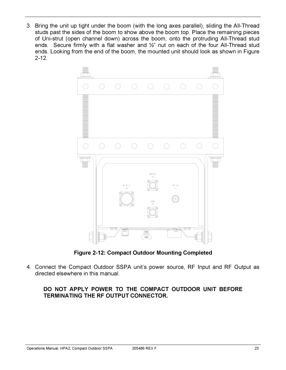
12 Compact Outdoor Mounting Completed
13 Outline Drawing, Compact Outdoor Mounting Kit
RF Output J2
Amplifier Enable Mute/Unmute J4
Operation
RF Input J1
Signal Type Function Pin
Monitor & Control Connector, J4
Open Collector Alarm Outputs J4
Alarms J4
Summary Alarm J4 Form C Contacts
Auxiliary Alarm J4 Form C Contacts
Serial I/O Control J4
RF Power Detector J4
Gain Adjust Input J4
RF Output Sample J3
Universal M&C Add Unit menu
Compact Outdoor Amplifier Quick Start Guide
Universal M&C Status Window
Signal Indicators
Voltage, Current and Temperature Display
Universal M&C Settings Window
Settings Window
High Temperature Alarm Threshold Range is 0 to 125 C
Power Up Settings
Spare Fault Wizard
Preferences Window
Universal M&C Preferences
Theory of Operation
Block Diagram, Compact Outdoor Amplifier
1 AC / DC Converter
Power Supply
Solid State Power Amplifier Module
EMI Filter and Transient Protection
Cooling System
Fan Boost Converter
This page Intentionally Left Blank
Spurious
Performance Tests
Gain and Gain Flatness
Input and Output Return Loss
IMD vs. Backoff for a 50W Ku Band Compact Outdoor Sspa
Intermodulation Distortion
Fan Removal
Maintenance
Cooling System Maintenance
Void your warranty
Fan Replacement
Connector Weatherproofing
Redundant System Concepts
Redundant System Operation
11 Redundant System with L Band input
Typical 11 Redundant System Outline
Compact Outdoor Amplifier in 11 Redundancy
Hardware Setup
11 System with RS232 Communication to each Amplifier
Software Setup
M&C Program Sspa Settings window
Operations Manual, HPA2, Compact Outdoor Sspa REV F
PC Control using RS232 and Paradise Universal M&C Software
10 Add New Compact Outdoor Sspa window
12 Paradise Datacom Universal M&C, Add Unit Menu Tree
15 Dialog window, Affirm mute of on-line amplifier
17 Unit1 Status panel showing Summary and Temperature Faults
PC Control using RS485 and Paradise M&C Software
19 11 Redundant System with RS485 Half Duplex Communication
20 12 Redundant System
12 Redundant Systems
22 Outline, 12 Redundant System
Schematic Redundant System
12 Redundant Systems with L Band Input
BUC
During Switch-Over, 10MHz is interrupted to Standby BUC
BUC
This page Intentionally Left Blank
Phase Combining Overview
Fixed Phase Combined Redundant Systems
11 Fixed Phase Combined System with FPRC-1100 controller
Signal Box Assembly
11 Fixed Phase Combined System Components
Outline, 11 Fixed Phase Combined System
FPRC-1100 Phase Combined System Controller
11 Fixed Phase Combined System Operation with the FPRC-1100
11 Phase Combined System with HPA control of BUC redundancy
11 Fixed Phase Combined System with L-Band Input
Redundant BUC Operation
Identifying a BUC Fault vs. Sspa Fault
Outline, 11 Fixed Phase Combined System with L-Band Input
Adjusting the Phase Combining
12 Fixed Phase Combined Systems
1 12 Fixed Phase Combined System Components
Outline, 12 Fixed Phase Combined System
HPA 1 & HPA 3 on line with HPA 2 on standby
12 Fixed Phase Combined System Operation with FPRC-1200
11 12 Fixed Phase Combined Compact Outdoor System
Output Power Adjustment
This page Intentionally Left Blank
Block Up Converter
Band Operation
Block Up Converter Overview
Zbuc Frequency Specifications
Zbuc Features
Smart Reference Technology
Zbuc RF output phase noise specification
Zbuc Theory of Operation
Zbuc FSK Monitor and Control
IFL Cable Considerations
Typical System Configuration
Common Coaxial Cable Characteristics
This page Intentionally Left Blank
Destination Address
Remote Control Interface
Serial Communication Protocol
Header Packet
Source Address
Command
Command Byte Values Command Name
Data Packet
Minimum valid Description Length of Data
Data Tag
Data Tag Byte Values
Tag Name
Data Field
Error Status / Data Address
Error Status Byte Values Error Code Name Possible Cause
Data Length
Frame Check
Timing issues
Trailer Packet
Response Frame Structure
Request Frame Structure
Data # Bytes Description Limits and Byte Values Address
System Settings Data Values
Data # Bytes Description Limits and valid values Dress
System Condition Addressing
System Threshold Data Values
ADC Analog-Digital Converter Addressing
10 Example 1 Host PC Request String
Examples
Example
Hex
11. Example 1 Sspa Response String
13. Example 2 Sspa Response String
12 Example 2 PC Request String
Operations Manual, HPA2, Compact Outdoor Sspa REV F
14. Example 3 PC Request String
15. Sspa Fault Status bit by bit description
Get Response designator
102 REV F Operations Manual, HPA2, Compact Outdoor Sspa
Remote Operation
Remote Operation
Main Menu Structure
Menu Structure
System Information menu structure
System Information sub-menu
106 REV F Operations Manual, HPA2, Compact Outdoor Sspa
Operation setup sub menu
Options menu
Aux. Action
Universal M&C Settings Screen, Modifying Protocol Select
Configuring Sspa and PC to work with terminal mode protocol
Connection Description window
Remote Terminal Set-up
COM Properties window
Example of Terminal Mode session
Appendix a Quick Start Cable
Figure A-1. Quick Start Cable Schematic Quick-Start Cable
114 REV F Operations Manual, HPA2, Compact Outdoor Sspa
Older Generation Compact Outdoor Sspa
Appendix B Alternate System Configurations
RCP2-1100
Table C-2 Unique Network Address Hardware Select †
Baud Select Lines on J4, Monitor & Control Connector
Appendix C Baud Select Lines on J4
Table C-1 Baud Rate and Protocol Reverting Options
118 REV F Operations Manual, HPA2, Compact Outdoor Sspa
Protocol Description
Power Up State
Appendix D Vsat BUC Protocol Support
Vsat BUC protocol support
Table D-3 Response Structure
Table D-2 Packet Structure
Value Power
Table D-4 Power Class Values†
122 REV F Operations Manual, HPA2, Compact Outdoor Sspa
Appendix E Documentation
124 REV F Operations Manual, HPA2, Compact Outdoor Sspa