FrameSaver� SLV
Copyright E 2000 Paradyne Corporation All rights reserved
Contents
Configuration
Security and Logins
Troubleshooting
Setting Up NetScout Manager Plus for FrameSaver Devices
Index
Document Organization
About This Guide
Purpose and Intended Audience
Where installation and setup information is located and how
Setting Up OpenLane for FrameSaver Devices. Identifies
Setting Up NetScout Manager Plus for FrameSaver
Devices. Describes setup of the NetScout Manager Plus
Product-Related Documents
Conventions Used
SLM Overview
About the FrameSaver SLV
SLM Overview
FrameSaver SLV 9664 Features
Maximum Number of PVCs and Management PVCs Supported
Feature FrameSaver SLV
March
9664-A2-GB20-00 March
About the FrameSaver SLV
User Interface Basic Operation
Logging On
If your login was Then
Procedure
Select
Main Menu
Screen Format Description
Screen Work Areas
Press
Navigating the Screens
Keyboard Keys
Select For the screen function Press Enter to
Function Keys
Selecting from a Menu
Switching Between Screen Areas
Example
Selecting a Field
Entering Information
User Interface and Basic Operation
Configuration
Configuration
Configuration Menu
Basic Configuration
Configuration Option Area Description
Configuration Option Areas
Main Menu → Configuration
Accessing and Displaying Configuration Options
Configuration → PVC Connections
Changing Configuration Options
Saving Configuration Options
Minimal Configuration Before Deploying Remote Units
Entering System Information Setting the System Clock
Main Menu → Control → System Information
If the selection is Enter
Setting Up Call Directories for Trap Dial-Out
Setting Up for Trap Dial-Out
Main Menu → Control → Modem Call Directories
Valid characters include For
Auto-Configuration Screen Example
Setting Up Auto-Configuration
Main Menu → Auto-Configuration
Discovery Mode Configuration Description
Selecting a Frame Relay Discovery Mode
Main Menu → Auto-Configuration → Frame Relay Discovery Mode
March
Automatically Removing a Circuit
Setting Up Local Management at the Central Site
Setting Up Management
Configuration → Data Ports → Dlci Records
Setting Up So the Router Can Receive RIP
Main Menu → Control → Change Operating Mode
Setting Up Back-to-Back Operation
Changing Operating Mode
Configuring the Overall System
Configuration Option Tables
Main Menu → Configuration → System → Frame Relay and LMI
Configuring Frame Relay and LMI for the System
System Frame Relay and LMI Options 1
LMI Behavior
System Frame Relay and LMI Options 2
LMI Status Enquiry N1 Possible Settings 1, 2, 3, 4
LMI Heartbeat T1 Possible Settings 5, 10, 15, 20, 25
Service Level Verification Options 1
Configuring Service Level Verification Options
SLV Packet Size bytes
Service Level Verification Options 2
SLV Timeout Clearing Event Threshold
Main Menu → Configuration → System → General
Configuring General System Options
Test Timeout
General System Options
Configuring the Network Interface
Configuring the Physical Interfaces
Main Menu → Configuration → Network → Physical
Network Physical Interface Options
Main Menu → Configuration → Data Ports → Physical
Configuring the User Data Port
User Data Port Physical Interface Options 1
Port Type
Monitor DTR
User Data Port Physical Interface Options 2
Monitor RTS Control
Port DTE Initiated Loopbacks
Interface Frame Relay Options 1
Configuring Frame Relay for an Interface
LMI Parameters
Interface Frame Relay Options 2
Main Menu→ Configuration→ Network/Data Ports→ Dlci Records
Manually Configuring Dlci Records
Interface Frame Relay Options 3
Dlci Record Options 1
Dlci Record Options 2
Dlci Type Possible Settings Standard, Multiplexed
CIR bps
Committed Burst Size Bc Bits
Excess Burst Size Bits
Dlci Record Options 3
Dlci Priority
Outbound Management Priority
PVC Connection Options 1
Configuring PVC Connections
Main Menu → Configuration → PVC Connections
Primary Destination Link
PVC Connection Options 2
Primary Destination Dlci
Primary Destination Edlci
Configuring Node IP Information
Setting Up Management and Communication Options
Node IP Options 1
Default IP Destination
TS Management Link
Node IP Options 2
Name
Configuring Management PVCs
10. Management PVC Options 1
Set DE
Primary Link Possible Settings Net1-FR1, Port-1, Clear
10. Management PVC Options 2
Primary Edlci
10. Management PVC Options 3
Primary Dlci
11. General Snmp Management Options
Configuring General Snmp Management
Telnet Login Required
Configuring Telnet and/or FTP Session Support
12. Telnet and FTP Session Options 1
Telnet Session
12. Telnet and FTP Session Options 2
Inactivity Timeout
Disconnect Time Minutes
FTP Session
FTP Max Receive Rate kbps
FTP Login Required
12. Telnet and FTP Session Options 3
Access Type
Configuring Snmp NMS Security Options
13. Snmp NMS Security Options
NMS IP Validation
14. Snmp Traps and Trap Dial-Out Options 1
Configuring Snmp Traps and Trap Dial-Out
Snmp Traps
Number of Trap Managers
Enterprise Specific Traps
14. Snmp Traps and Trap Dial-Out Options 2
Initial Route Destination
14. Snmp Traps and Trap Dial-Out Options 3
Link Traps Possible Settings Disable, Up, Down, Both
Link Traps Interfaces
Dlci Traps on Interfaces
14. Snmp Traps and Trap Dial-Out Options 4
Dial-Out Delay TIme Min
Trap Dial-Out
Trap Disconnect
Alternate Dial-Out Directory
14. Snmp Traps and Trap Dial-Out Options 5
15. Communication Port Options 1
Configuring the Communication Port
Port Use
Character Length
15. Communication Port Options 2
Login Required
Stop Bits
Ignore Control Leads
15. Communication Port Options 3
Link Protocol
15. Communication Port Options 4
External Modem Commands
Configuring the COM Port to Support an External Modem
Dial-In Access
16. External Modem COM Port Options 1
16. External Modem COM Port Options 2
Security and Logins
Controlling Asynchronous Terminal Access
Limiting Access
Set the configuration option
Controlling Telnet or FTP Access
Controlling External COM Port Device Access
Limiting Telnet Access
Limiting FTP Access
Limiting Telnet or FTP Access Over the TS Management Link
Disabling Snmp Access
Controlling Snmp Access
Assigning Snmp Community Names and Access Levels
Limiting Snmp Access Through IP Addresses
Field Enter
Creating a Login
Main Menu → Control → Administer Logins
Deleting a Login
Modifying a Login
Operation and Maintenance
View this field To find
Displaying System Information
Main Menu → Status → Identity
Display LEDs & Control Leads Screen
Viewing LEDs and Control Leads
Main Menu → Status → Display LEDs and Control Leads
General Status LEDs Label Indication Color What It Means
LED Descriptions
User Data Port LED Label Indication Color What It Means
Control Lead Descriptions
Network Interface LED Label Indication Color What It Means
Device Messages 1 What It Indicates What To Do
Device Messages
Device Messages 2 What It Indicates What To Do
Device Messages 3 What It Indicates What To Do
Software
Device Messages 4 What It Indicates What To Do
Device Messages 5 What It Indicates What To Do
Status Menu
Status Information
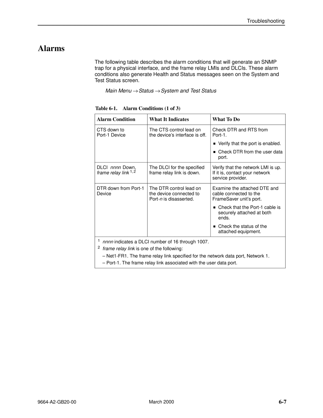
Main Menu → Status → System and Test Status
System and Test Status Messages
Self-Test Results Messages
Self-Test Results Messages
Health and Status Messages 1 What It Indicates
Health and Status Messages
LMI Down, frame relay link
Health and Status Messages 2 What It Indicates
Test Status Messages What It Indicates
Test Status Messages
LMI-Reported DLCIs Status Screen Example
Network LMI-Reported DLCIs Status
Main Menu → Status → LMI Reported DLCIs
Status What It Indicates
Network LMI-Reported DLCIs Status Field
Main Menu → Status → PVC Connection Status
PVC Connection Status
PVC Connection Status Screen Example
10. PVC Connection Status 1 Field
10. PVC Connection Status 2 Field What It Indicates
11. Network Interface Status 1 Field What It Indicates
Network Interface Status
Main Menu → Status → Network Interface Status
INFO0 INFO2
11. Network Interface Status 2 Field What It Indicates
Performance Statistics Menu
Performance Statistics
Main Menu → Status → Performance Statistics
Performance Statistics → Frame Relay
Clearing Performance Statistics
Performance Statistics → Clear All Statistics
Service Level Verification Performance Statistics
Average round trip latency is measured every SLV sampling
13. Dlci Performance Statistics 1 What It Indicates
Dlci Performance Statistics
Main Menu → Status → Performance Statistics → Dlci
13. Dlci Performance Statistics 2 What It Indicates
Frame Relay Performance Statistics
Frame Relay Errors
Main Menu → Status → Performance Statistics → Frame Relay
14. Frame Relay Performance Statistics 1 What It Indicates
Frame Relay LMI
Frame Relay Errors contd
14. Frame Relay Performance Statistics 2 What It Indicates
14. Frame Relay Performance Statistics 3 What It Indicates
Frame Relay Hdlc Errors
FTP File Transfers
Dir directory
Command Definition
If the message displayed is Then
Upgrading System Software
Changing Software
Determining Whether a Download Is Completed
If retrieving Then
Transferring Collected Data
Operation and Maintenance
Troubleshooting
Indicators See
Problem Indicators
Resetting the Unit By Cycling the Power
Resetting the Unit and Restoring Communication
Resetting the Unit from the Control Menu
If selecting Following occurs
Restoring Communication with a Misconfigured Unit
Main Menu → Control → LMI Packet Capture Utility
Troubleshooting Management Link Feature
LMI Packet Capture Utility Feature
LMI Trace Log Example
LMI Packet Capture Utility → Display LMI Trace Log
Alarm Conditions 1 What It Indicates What To Do
Alarms
Alarm Conditions 2 What It Indicates What To Do
Alarm Conditions 3 What It Indicates What To Do
Device Problems Symptom Possible Cause Solutions
Troubleshooting Tables
Device Problems
Frame Relay PVC Problems Symptom Possible Cause Solutions
Frame Relay PVC Problems
Test Menu Example
Test Timeout Feature
Tests Available
Aborting All Tests
When the status of a test is Only command available is
Starting and Stopping a Test
PVC Tests Screen Example
PVC Tests
Send Pattern
Network or Port Internal PVC Loopback
Main Menu → Test → Network PVC Tests → PVC Loopback
Main Menu → Test → Data Port PVC Tests → PVC Loopback
Connectivity
Monitor Pattern
Main Menu → Test → Data Port Physical Tests
Physical Tests
DTE Loopback
Main Menu → Test → IP Ping
IP Ping Test
Main Menu → Test → Lamp Test
Lamp Test
Troubleshooting
OpenLane Support of FrameSaver Devices
Setting Up OpenLane for FrameSaver Devices
OpenLane Support of FrameSaver Devices
Setting Up FrameSaver SLV Support
Setting Up the OpenLane SLM System
Setting Up NetScout Manager Plus for FrameSaver Devices
Before Getting Started
Alarms
Properties
User history
Configuring NetScout Manager Plus
Procedure
Verifying Domains and Groups
Correcting Domains and Groups
Property Description Setting
Adding SLV Alarms Using a Template
Editing Alarms
March
Adding SLV Alarms Manually
Paradyne
Field Select or Enter
Creating History Files
Procedure
Dvuhist -f Dallas51 3 config 30 60 Dallas51k.udh
Installing the User-Defined History Files
Monitoring a DLCIs History Data
9664-A2-GB20-00 March
Monitoring the Agent Using NetScout Manager Plus
Procedure
Traffic Statistics Protocol Statistics
Statistical Windows Supported
Setting Up Network Health for FrameSaver Devices
Installation and Setup of Network Health
Discovering FrameSaver Elements
Configuring the Discovered Elements
Grouping Elements for Reports
About At-a-Glance Reports
About Service Level Reports
Generating Reports for a Group
Printed Reports
Reports Applicable to SLV Devices
About Trend Reports
March
9664-A2-GB20-00 March
Setting Up Network Health for FrameSaver Devices
Menus
Menu Hierarchy
Status
Menu Hierarchy
Configuration
Menu Hierarchy
Snmp MIBs and Traps, Rmon Alarm Defaults
Downloading MIBs and Snmp Traps
MIB Support
FrameSaver Units sysObjectID system
System Group mib-2
FrameSaver Units sysDescr system
Paradyne Indexes to the Interface Table ifTable
Interfaces Group mib-2
Physical Layer
Frame Relay Logical Layer
Interface number Dlci number ALL
NetScout Indexes to the Interface Table ifTable
Standards Compliance for Snmp Traps
Trap warmStart
Trap authenticationFailure
Table B-3. warmStart Trap What It Indicates Possible Cause
Variable-Binding
Traps linkUp and linkDown
Physical Sublayer
Strings
Logical Link Sublayer
DevHealthAndStatus
Traps enterprise-Specific
SLVs devFrExt.mib
Traps RMON-Specific
Event Defaults
Rmon Alarm and Event Defaults
EventIndex EventDescription EventType EventCommunity
Rising Event Operation
Network Isdn S/T Physical Interface Alarm Defaults
Frame Relay Link Alarm Defaults
Snmp MIBs and Traps, and Rmon Alarm Defaults
Dlci Alarm Defaults ± Paradyne Area
Dlci Alarm Defaults ± NetScout Area
Tx CIR Utilization
Object ID Cross-References Numeric Order
6.1.2.1.16.12.2.1
6.1.2.1.2.2.1
6.1.2.1.2.10.32.2.1
6.1.4.1.1795.2.24.2.6.9.4
6.1.4.1.1795.2.24.2
Dlci EIR
6.1.4.1.1795.2.24.2.6.9.4.10.3.1
6.1.4.1.1795.2.24.2.6.9.4.5.2.1
6.1.4.1.1795.2.24.2.6.9.4.7.1
6.1.2.1.10.32.2.1
Snmp MIBs and Traps, and Rmon Alarm Defaults
Snmp MIBs and Traps, and Rmon Alarm Defaults
Rear Panel
Connectors, Cables, Pin Assignments
COM Port-to-Terminal Cable Feature No -F2-540
COM Port Connector
Signal Direction Pin #
COM Port Non-Keyed
Cable Plug to Modular Jack LAN Adapter
LAN Adapter Converter and Cable
Plug-to-Modular Jack Converter Com Port Position DB25 Plug
Pin
Standard EIA-232 Crossover Cable
AT Command String To configure the modem to
Signal Direction Pin Numbers
Network Connector
Isdn Modular Cable
Function Direction Pin Number
Direction Pin Pin #
User Data Port Connector
Signal Circuit Mnemonic
Signal 25-Pin
DTE Adapter Cable Feature No -F1-571
Plug
Direction Pin Socket Pin #
DTE Adapter Feature No -F1-570
DTR
EIA-530 Straight-through Cable Feature No -F1-523
ITU
Technical Specifications
User Data Port
Network Interface
Equipment
Model / Feature Number
Equipment List
Cables
Description Part Number Feature Number
Numbers
Index
IN-2
IN-3
IN-4
IN-5
IN-6
IN-7
IN-8
IN-9
IN-10