LEDs
3
LED Locations
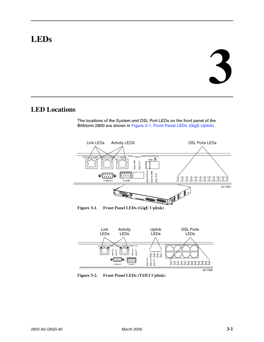
The locations of the System and DSL Port LEDs on the front panel of the
BitStorm 2600 are shown in Figure 3-1, Front Panel LEDs (GigE Uplink).
Link LEDs Activity LEDS
PORT3 |
LINK | ACT | GigE |
|
|
| ||
| STATUS | ALARM | TEST |
CONSOLE | ALARM |
DSL Ports LEDs
1 | 3 | 5 | 7 | 9 | 11 | 13 | 15 | 17 | 19 | 21 | 23 |
2 | 4 | 6 | 8 | 10 | 12 | 14 | 16 | 18 | 20 | 22 | 24 |
Figure 3-1. Front Panel LEDs (GigE Uplink)
Link | Activity | Uplink | DSL Ports |
LEDs | LEDs | LEDs | LEDs |
![]()
![]()
![]()
![]()
LINK | ACT | LINK | ACT | UPLINK PORTS | |||
|
|
|
| 1 | 3 | 5 | 7 |
|
|
| STATUS | 2 | 4 | 6 | 8 |
|
|
| ALARM | TEST |
|
| |
CONSOLE ALARM
Figure 3-2. Front Panel LEDs (T1/E1 Uplink)
1 ![]() 3
3 ![]() 5
5 ![]() 7
7 ![]() 9
9 ![]() 11
11 ![]() 13
13 ![]() 15
15 ![]() 17
17 ![]() 19
19 ![]() 21
21 ![]() 23
23
24 6 8 10 12 14 16 18 20 22 24
March 2005 |