Communications—P5 Connector
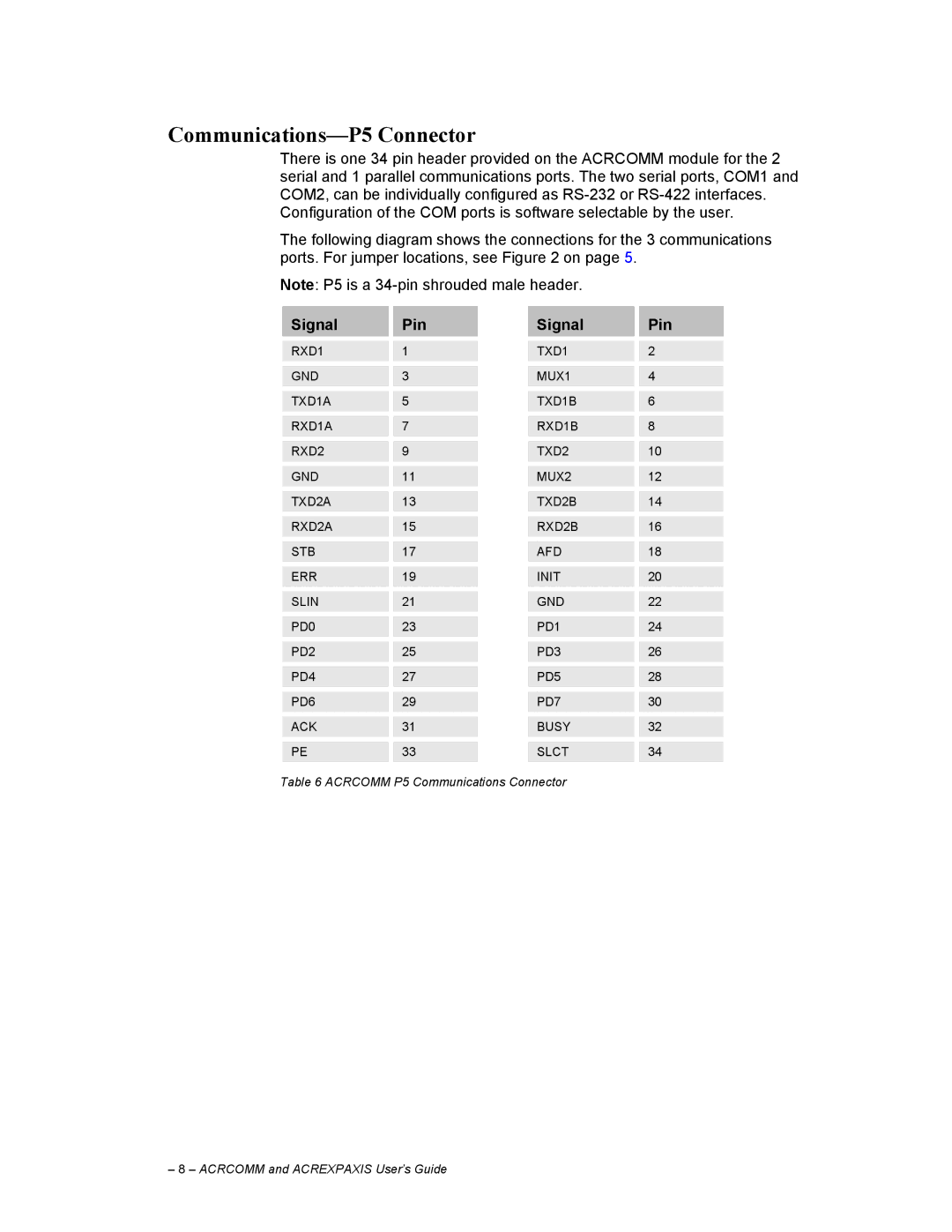
There is one 34 pin header provided on the ACRCOMM module for the 2 serial and 1 parallel communications ports. The two serial ports, COM1 and COM2, can be individually configured as
The following diagram shows the connections for the 3 communications ports. For jumper locations, see Figure 2 on page 5.
Note: P5 is a
Signal |
| Pin |
| Signal |
| Pin |
|
|
|
|
| ||
RXD1 |
| 1 |
| TXD1 |
| 2 |
|
|
|
|
| ||
GND |
| 3 |
| MUX1 |
| 4 |
|
|
|
|
| ||
TXD1A |
| 5 |
| TXD1B |
| 6 |
|
|
|
|
| ||
RXD1A |
| 7 |
| RXD1B |
| 8 |
|
|
|
|
| ||
RXD2 |
| 9 |
| TXD2 |
| 10 |
|
|
|
|
| ||
GND |
| 11 |
| MUX2 |
| 12 |
|
|
|
|
| ||
TXD2A |
| 13 |
| TXD2B |
| 14 |
|
|
|
|
| ||
RXD2A |
| 15 |
| RXD2B |
| 16 |
|
|
|
|
| ||
STB |
| 17 |
| AFD |
| 18 |
|
|
|
|
| ||
ERR |
| 19 |
| INIT |
| 20 |
|
|
|
|
| ||
SLIN |
| 21 |
| GND |
| 22 |
|
|
|
|
| ||
PD0 |
| 23 |
| PD1 |
| 24 |
|
|
|
|
| ||
PD2 |
| 25 |
| PD3 |
| 26 |
|
|
|
|
| ||
PD4 |
| 27 |
| PD5 |
| 28 |
|
|
|
|
| ||
PD6 |
| 29 |
| PD7 |
| 30 |
|
|
|
|
| ||
ACK |
| 31 |
| BUSY |
| 32 |
|
|
|
|
| ||
PE |
| 33 |
| SLCT |
| 34 |
|
|
|
|
|
|
|
Table 6 ACRCOMM P5 Communications Connector
– 8 – ACRCOMM and ACREXPAXIS User’s Guide