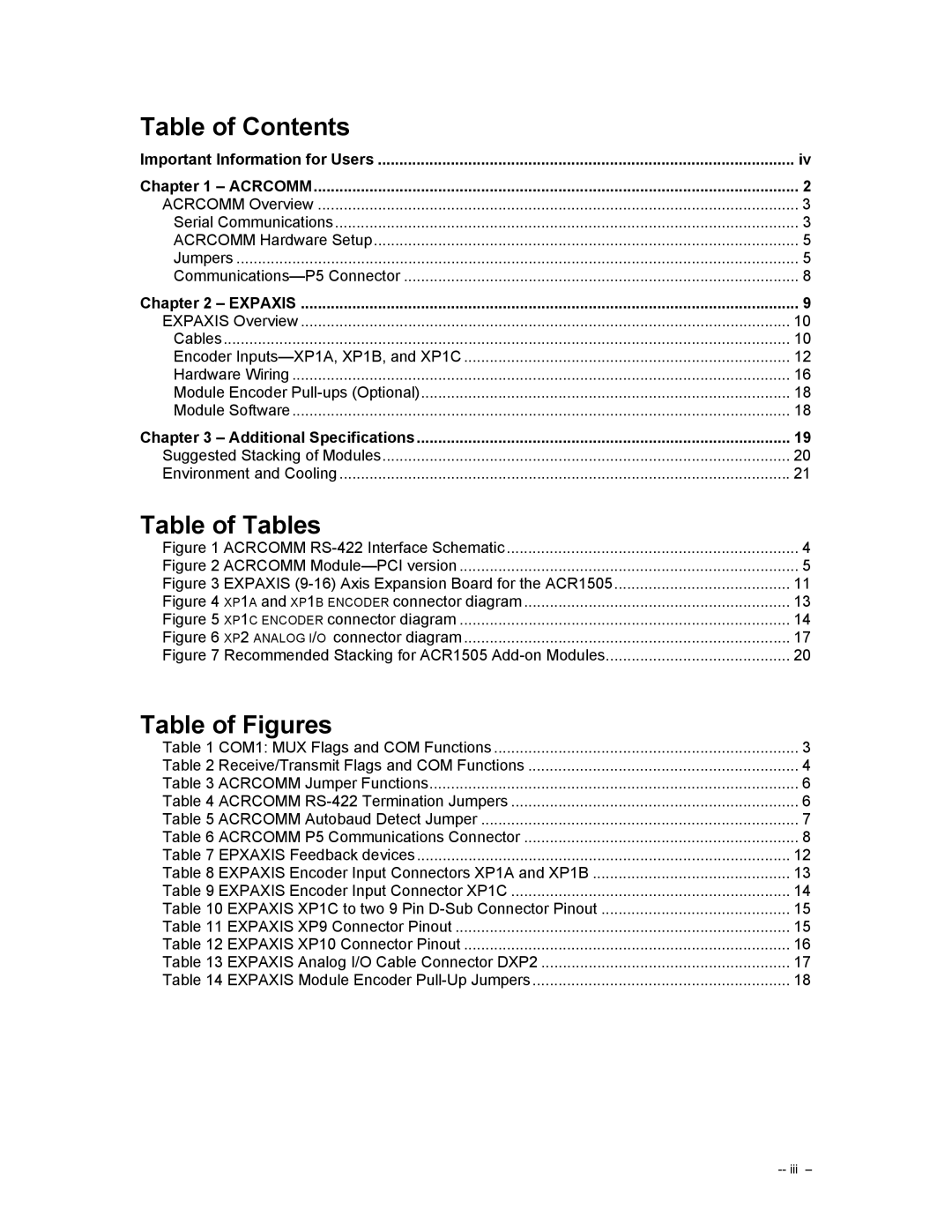
Table of Contents |
|
Important Information for Users | iv |
Chapter 1 – ACRCOMM | 2 |
ACRCOMM Overview | 3 |
Serial Communications | 3 |
ACRCOMM Hardware Setup | 5 |
Jumpers | 5 |
8 | |
Chapter 2 – EXPAXIS | 9 |
EXPAXIS Overview | 10 |
Cables | 10 |
Encoder | 12 |
Hardware Wiring | 16 |
Module Encoder | 18 |
Module Software | 18 |
Chapter 3 – Additional Specifications | 19 |
Suggested Stacking of Modules | 20 |
Environment and Cooling | 21 |
Table of Tables |
|
Figure 1 ACRCOMM | 4 |
Figure 2 ACRCOMM | 5 |
Figure 3 EXPAXIS | 11 |
Figure 4 XP1A and XP1B ENCODER connector diagram | 13 |
Figure 5 XP1C ENCODER connector diagram | 14 |
Figure 6 XP2 ANALOG I/O connector diagram | 17 |
Figure 7 Recommended Stacking for ACR1505 | 20 |
Table of Figures |
|
Table 1 COM1: MUX Flags and COM Functions | 3 |
Table 2 Receive/Transmit Flags and COM Functions | 4 |
Table 3 ACRCOMM Jumper Functions | 6 |
Table 4 ACRCOMM | 6 |
Table 5 ACRCOMM Autobaud Detect Jumper | 7 |
Table 6 ACRCOMM P5 Communications Connector | 8 |
Table 7 EPXAXIS Feedback devices | 12 |
Table 8 EXPAXIS Encoder Input Connectors XP1A and XP1B | 13 |
Table 9 EXPAXIS Encoder Input Connector XP1C | 14 |
Table 10 EXPAXIS XP1C to two 9 Pin | 15 |
Table 11 EXPAXIS XP9 Connector Pinout | 15 |
Table 12 EXPAXIS XP10 Connector Pinout | 16 |
Table 13 EXPAXIS Analog I/O Cable Connector DXP2 | 17 |
Table 14 EXPAXIS Module Encoder | 18 |
Page 3
Image 3
