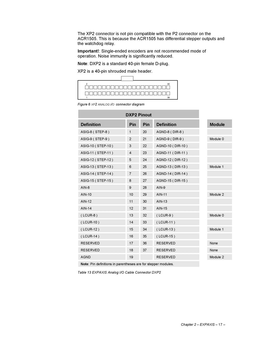
The XP2 connector is not pin compatible with the P2 connector on the ACR1505. This is because the ACR1505 has differential stepper outputs and the watchdog relay.
Important!:
Note: DXP2 is a standard
Figure 6 XP2 ANALOG I/O connector diagram
| DXP2 Pinout |
|
|
|
| |||
|
|
|
|
|
|
|
|
|
Definition |
| Pin |
| Pin |
| Definition |
| Module |
|
|
|
|
|
|
| ||
| 1 |
| 20 |
|
|
| ||
|
|
|
|
|
|
| ||
| 2 |
| 21 |
|
| Module 0 | ||
|
|
|
|
|
|
| ||
| 3 |
| 22 |
|
|
| ||
|
|
|
|
|
|
| ||
| 4 |
| 23 |
|
|
| ||
|
|
|
|
|
|
| ||
| 5 |
| 24 |
|
|
| ||
|
|
|
|
|
|
| ||
| 6 |
| 25 |
|
| Module 1 | ||
|
|
|
|
|
|
| ||
| 7 |
| 26 |
|
|
| ||
|
|
|
|
|
|
| ||
| 8 |
| 27 |
|
|
| ||
|
|
|
|
|
|
| ||
| 9 |
| 28 |
|
|
| ||
|
|
|
|
|
|
| ||
| 10 |
| 29 |
|
| Module 2 | ||
|
|
|
|
|
|
| ||
| 11 |
| 30 |
|
|
| ||
|
|
|
|
|
|
| ||
| 12 |
| 31 |
|
|
| ||
|
|
|
|
|
|
| ||
( |
| 13 |
| 32 |
| ( |
| Module 0 |
|
|
|
|
|
|
| ||
( |
| 14 |
| 33 |
| ( |
|
|
|
|
|
|
|
|
| ||
( |
| 15 |
| 34 |
| ( |
| Module 1 |
|
|
|
|
|
|
| ||
( |
| 16 |
| 35 |
| ( |
|
|
|
|
|
|
|
|
| ||
RESERVED |
| 17 |
| 36 |
| RESERVED |
| None |
|
|
|
|
|
|
| ||
RESERVED |
| 18 |
| 37 |
| RESERVED |
| None |
|
|
|
|
|
|
|
| |
AGND |
| 19 |
|
|
| RESERVED |
| Module 2 |
Note: Pin definitions in parentheses are for stepper modules.
Table 13 EXPAXIS Analog I/O Cable Connector DXP2
Chapter 2 – EXPAXIS – 17 –
