Super Modular Multi System AIR Conditioner
Adoption of NEW Refrigerant
Contents
Separate sold parts
Refrigerant piping
Cable 3-core 2.5mm2, in conformity with Design 60245 IEC57
New Refrigerant Air Conditioner Installation
Precautions for Safety
Precautions for Safety
Selection of Installation Place
Pipe connecting position
Installation space
Front view
Bottom view
Selection of Installation Place
Installation of Indoor Unit
Case of wireless type
„ In case of wooden construction Wide wall
Installation of installation plate
„ In case of reinforced concrete construction
„ In case of rear direction piping
Installation of indoor unit
Installation of Indoor Unit
Drain Piping Work
Installation of remote controller Sold separately
Piping and Insulation
Pipe and Drain hose formation
Refrigerant Piping
Piping material and dimensions
Permissible pipe length and permissible height difference
Pipe Forming/End Positioning
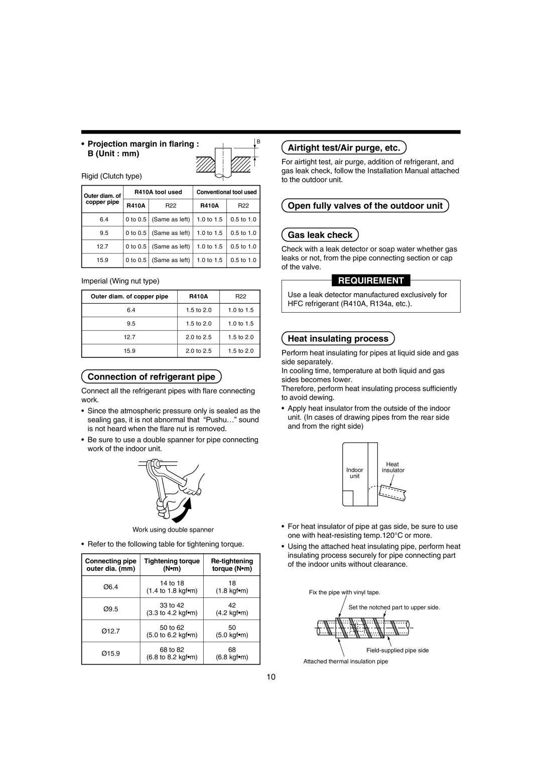
Airtight test/Air purge, etc
Connection of refrigerant pipe
Open fully valves of the outdoor unit Gas leak check
Heat insulating process
Be sure to install an earth leakage breaker
Power supply specifications
Electric Work
Indoor/Outdoor inter-unit wiring, Central controller wiring
Indoor unit power supply *1
Remote controller wiring
Cable connection
Wiring between indoor and outdoor units
Remote controller wiring
Address setup
Wiring diagram
Basic operation procedure for setup exchange
Exchange of applicable control setup
Applicable Controls
Notification
Applicable Controls
Adjustment of air direction
Change of lighting time of filter sign
To secure better effect of heating
Case of wired remote controller
How to execute test operation
Procedure
Test RUN
Test RUN
Case of wireless remote controller
Confirmation of error history
Troubleshooting
Confirmation and check
Check code list
Troubleshooting
Check method
Terminology
ALT
Error detected by TCC-LINK central control device
Display on sensor part of wireless
Display on wired remote controller
New check code
Special mention
Pièces vendues séparément
Tuyaux de réfrigérant
Utilisation
Nom de la pièce Quantité Forme
Avertissement
Mesures DE Securite
Pour déconnecter l’appareil du secteur
Branchez correctement le câble de raccordement
Mesures DE Securite
Selection DU Lieu D’INSTALLATION
Position de raccordement de tuyau
Espace requis pour l’installation
Vue avant
Vue du bas
Selection DU Lieu D’INSTALLATION
Installation DE L’UNITE Interieure
Sur les types sans-fil
„ Dans une construction en bois mur large
Installation de la plaque d’installation
„ Sur les construction en béton armé
„ Lorsque la tuyauterie est orientée vers l’arrière
Installation de l’unité intérieure
Installation DE L’UNITE Interieure
„ Enlèvement de la plaque droite de l’unité intérieure
„ Lorsque la tuyauterie est orientée vers la gauche
Prudence
Installation de la télécommande vendue séparément
Tuyauterie et isolation
Formation du tuyau et du tuyau flexible d’évacuation
Dimension en mètres du Diamètre de ’évasement a Unité
Tuyauterie et dimensions
Tuyaux DE Réfrigérant
Mise en forme/Pose définitive des tuyaux
Test d’étanchéité/Purge d’air, etc
Raccordement du tuyau de réfrigérant
Procédé de calorifugeage
Marge de projection de ’évasement Unité mm
Caractéristiques de l’alimentation électrique
Travaux D’ÉLECTRICITÉ
Assurez-vous de raccorder le fil de terre. Mise à la terre
Raccordement des câbles
Câbles de la télécommande *4
Alimentation électrique de l’unité intérieure *1
Configuration de l’adresse
Raccordement des télécommandes
Travaux D’ÉLECTRICITÉ
Câblage de liaison entre unités intérieure et extérieure
Modification de la configuration de la commande possible
Commandes Utilisables
Procédure de base pour modifier la configuration
Adresses automatiques
Commande de groupe
Commandes Utilisables
Modification du temps d’éclairage de la minuterie du filtre
Pour garantir un meilleur chauffage
En cas de télécommande avec fil
Mode d’exécution d’un essai de fonctionnement
Essai DE Fonctionnement
Remarque
Essai DE Fonctionnement
Avec une télécommande sans-fil
Procédure
Confirmation et vérification
Dépannage
Confirmation de l’historique de pannes
Liste des codes de vérification
Dépannage
Terminologie
Afficheur extérieur à 7 segments
Principale Code auxiliaire Centrale AI NET
Affichage sur capteur télécommande sans-fil
Affichage sur télécommande à fil
Affichage sur indicateur du récepteur télécommande sans-fil
Nouveau code de vérification
Getrennt erhältliche Teile
Kühlmittel-Leitungssystem
Adrig 2.5 mm², entsprechend 60425 IEC57
Warnung
Sicherheitsvorkehrungen
Vorsicht Trennen des Geräts von der Hauptstromversorgung
Sicherheitsvorkehrungen
Auswahl DES Aufstellungsortes
Vorsicht
Rohrleitungsanschluss
Platzbedarf
Vorderansicht
Ansicht von unten
Auswahl DES Aufstellungsortes
Installation DER Raumeinheit
Für drahtlose Fernbedienungen
„ Bei Holzkonstruktionen Holzständerwand
Installation der Montageplatte
„ Bei Stahlbetonwänden
„ Rohrleitungsführung nach hinten
Installation der Inneneinheit
Installation DER Raumeinheit
Rohrleitungen und Isolierung
Installation der Fernbedienung getrennt erhältlich
Anordnung von Rohrleitungen und Kondensatschlauch
Rohrleitungen
Erlaubte Rohrleitungslängen und erlaubte Höhendifferenzen
Kühlmittelleitungen
Rohrmaterial und Abmessungen
Biegen und Positionieren
Anschluss der Kühlmittelleitung
Dichtetest/Entlüftung usw
Wärmeisolierung
Bördelhöhe B Einheit mm
Spezifikation der Stromversorgung
Elektroarbeiten
Verlegen Sie auch eine Masseleitung. Masse anschließen
Stromversorgung Raumeinheit
Kabelanschlüsse
Verkabelung der Fernbedienung
Verkabelung der Fernbedienung
Elektroarbeiten
Verbindungskabel zwischen Raum- und Außeneinheit
Adress-Einstellung
Hinweise
Steuerungsmöglichkeiten
Änderung der Steuerungsvorgaben
Automatische Adressierung
Änderung der Zeitvorgabe für die Filterwarnleuchte
Steuerungsmöglichkeiten
Verbesserung der Heizleistung
Einstellung der Lüftungsrichtung
Hinweis
Testlauf
Vorbereitung
Ablauf des Tests
Infrarot-Fernbedienung
Testlauf
Bestätigung und Prüfung
Fehlersuche
Aufruf des Fehlerspeichers
Liste der Fehlercodes
Fehlersuche
Funktion Uhr Bereit Blinken F01
C06 C12
Fehler durch zentrale Überwachung TCC-LINK erkannt
Anzeige bei verdrahteter Fernbedienung
Neuer Prüfcode
Anzeige auf Empfangsteil der Infrarot-Fernbedienung
Spezielle Bemerkung
Parti da acquistare a parte
Tubazioni del refrigerante
Utilizzo
SForma
Avvertenza
Precauzioni PER LA Sicurezza
Attenzione
Collegare il cavo di connessione in modo corretto
Evitare l’installazione nei posti seguenti
Scelta DEL Posto D’INSTALLAZIONE
Precauzioni PER LA Sicurezza
Posizione di connessione del tubo
Spazio per l’installazione
Vista anteriore
Vista dal basso
Scelta DEL Posto D’INSTALLAZIONE
Installazione DELL’UNITÀ Interna
Nel caso del tipo via radio
„ Nel caso di una costruzione di legno muro laterale
Installazione della piastra per l’installazione
„ Nel caso di tubo in direzione posteriore
Modello MMK Peso kg Da 0071H a 0121H Da 0151H a 0181H 0241H
Installazione dell’unità interna
Installazione DELL’UNITÀ Interna
„ Nel caso di tubo in direzione posteriore e destra
„ Nel caso di tubo in direzione sinistra
Lavoro PER LA Tubazione DI Scarico
Installazione del pannello del soffitto in vendita a parte
Tubazione e isolamento
Sinistro o sul lato destro dell’unità
Svasatura Dimensione misuratore dia Svasatura a Unità mm
Materiale per tubature e dimensioni
Tubazioni DEL Refrigerante
Formatura tubi/Posizionamento estremità
Connessione del tubo del refrigerante
Prove di tenuta d’aria/Sfiato aria, ecc
Procedura per isolamento termico
Margine di protezione Svasatura Unità mm
Collegamenti Elettrici
Installare un interruttore di collegamento a terra
Dati tecnici per alimentazione elettrica
Alimentazione elettrica dell’unità interna
Collegamento dei cavi
Collegamenti elettrici del telecomando
Collegamenti Elettrici
Schema dei collegamenti elettrici
Posa in opera dei cavi per il telecomando
Collegamenti elettrici fra unità interna e esterna
Avviso
Comandi Applicabili
Scambio di impostazioni dei comandi applicabili
Indirizzamento automatico
Modifica del tempo di accensione del simbolo del filtro
Comandi Applicabili
Per garantire una resa migliore del riscaldamento
Regolazione della direzione dell’aria
Nota
Funzionamento DI Prova
Prima del funzionamento di prova
Come avviare il funzionamento di prova
Caso di telecomando via radio
Funzionamento DI Prova
Conferma della casistica di errori
Risoluzione DEI Problemi
Conferma e controllo
Lista dei codici di controllo
Risoluzione DEI Problemi
Terminologia
Errore sensore TCJ unità interna
Errore motore ventola unità interna
Nuovo codice di controllo
Componentes vendidos por separado
Tubería de refrigerante
Nombre del
Utilización
Precaución
Precauciones Para SU Seguridad
Advertencia
Conecte el cable de conexión correctamente
Precauciones Para SU Seguridad
Selección DEL Lugar DE Instalación
Evite la instalación en los siguientes lugares
Posición de conexión de la tubería
Espacio de instalación
Vista frontal
Vista inferior
Selección DEL Lugar DE Instalación
Instalación DE LA Unidad Interior
En el caso de mando a inalámbrico
„ En casos de construcciones en madera Muro ancho
Montaje de la placa de instalación
„ En caso de construcciones de hormigón armado
„ Para los tubos posteriores
Instalación de la unidad de interior
Instalación DE LA Unidad Interior
„ Para los tubos posteriores y del lado derecho
„ Para los tubos laterales derechos
Tubería
Formación del tubo y el desagüe
Tubería DE Regrigerante
Material y dimensiones de la tubería
Longitud del tubo y diferencia de altura permisibles
Moldeado de los tubos / Posición final
Conexión del tubo de refrigerante
Prueba de hermetizado, purga de aire, etc
Proceso de aislamiento térmico
Margen de proyección en El abocinado Unidad mm
Especificaciones de la alimentación eléctrica
Instalación Eléctrica
Instale un disyuntor de fugas a tierra
Alimentación eléctrica de la unidad interior
Conexión de los cables
Cableado del mando a distancia
Diagrama del cableado
Configuración de las identificaciones
Instalación Eléctrica
Cableado del mando a distancia
Procedimiento básico para cambiar la configuración
Cambio en la configuración de los controles aplicables
Controles Aplicables
Notificación
Cambiar momento de encendido de la señal de filtro
Controles Aplicables
Para mejorar el efecto calefactor
Ajustes para la dirección del aire
Antes de llevar a cabo la prueba
Prueba DE Funcionamiento
Cómo realizar una prueba de funcionamiento
En el caso de mando a distancia con cable
En caso de utilizar un control remoto inalámbrico
Prueba DE Funcionamiento
Confirmación del historial de errores
Resolución DE Problemas
Confirmación y verificación
Lista de códigos de verificación
Resolución DE Problemas
Terminología
108
109
Nuevo código de verificación
Peças vendidas em separado
Tubagem de refrigerante
Desenhada 60245 IEC57
Precauções
Precauções DE Segurança
Aviso
Instalação de Ar Condicionado de Novo Refrigerante
Precauções DE Segurança
Selecção do Local DE Instalação
Cuidado
Evite instalar a unidade nos seguintes locais
Posição da ligação dos tubos
Espaço de instalação
Tubo do lado da Peças a serem removidas Tubagem
Selecção do Local DE Instalação
Instalação DA Unidade Interior
No caso do tipo sem cabos
„ No caso de construção de Madeira Parede de madeira
Instalação da chapa de instalação
„ No caso de construção de betão armado
„ No caso de tubagem direccionada para trás
Instalação da unidade interior
Instalação DA Unidade Interior
„ Remover o painel do lado direito da unidade interior
„ No caso de tubagem do direccionada para o lado esquerdo
Ciudado
Instalação DA Tubagem DE Drenagem
Tubagem e isolamento
Formação dos tubos e mangueira de drenagem
Material e dimensões de tubagem
Tubagem DE Refrigerante
Definição da Tubagem / Posição dos Extremos
Alargamento Diâmetro de alargamento Unidade mm
Teste de hermeticidade/Purga de ar, etc
Ligação do tubo de refrigerante
Processo de isolamento térmico
Especificações da alimentação eléctrica
Trabalhos DE Electricidade
Não se esqueça de ligar o cabo de terra. Ligação à terra
Alimentação eléctrica da unidade interior
Ligação de cabos
Cabos do controlador remoto
Trabalhos DE Electricidade
Diagrama de ligações
Ligações do controlador remoto
Ligações entre as unidades interiores e exteriores
Procedimento da operação básica para troca de configuração
Troca da configuração de controlo aplicável
Controlos Aplicáveis
Endereçamento automático
Mude o tempo de iluminação do sinal do filtro
Controlos Aplicáveis
Para garantir um melhor efeito do aquecimento
Ajuste da direcção do ar
Avisos
Teste DE Funcionamento
Antes do teste de funcionamento
Como efectuar um teste
No caso de controlador remoto sem cabos
Teste DE Funcionamento
Confirmação e verificação
Resolução DE Problemas
Confirmação de historial de erros
Procedimento
Lista de códigos de erros
Resolução DE Problemas
130
Erro detectado pelo dispositivo de controlo central TCC-LINK
Novo código de verificação
Niet meegeleverde onderdelen
Koelmiddelleidingen
Toepassing
Vorm
LET OP
Installeren van een airconditioner met een nieuw koelmiddel
Waarschuwing
Het apparaat loskoppelen van de netvoeding
Voorzorgsmaatregelen Voor UW Veiligheid
Installeer de airconditioner niet op de volgende plaatsen
Leidingaansluitingspositie
Installatieruimte
Vooraanzicht
Onderaanzicht
Keuze VAN DE Locatie Voor DE Installatie
Installatie VAN DE Binnenunit
Bij een draadloos model
„ Bij installatie van de leidingen via de achterzijde
De installatieplaat installeren
„ Bij een houten constructie holle wand
„ Bij een constructie uit gewapend beton
Installatie van de binnenunit
Installatie VAN DE Binnenunit
„ Bij installatie van de leidingen via de linkerzijde
„ Bij installatie van de leidingen via de rechterzijde
Leidingen en isolatie
Afvoerleidingen
Leidingen en afvoerslang buigen
Toegestane leidinglengte en hoogteverschil
Koelmiddelleidingen
Leidingmateriaal en -afmetingen
Leidingen buigen Bepalen van het uiteinde van de leidingen
Gasdichtheid testen Ontluchten enzovoort
Aansluiten van koelmiddelleidingen
Isoleren
Uitstekende leidinglengte Bij trompen Eenheid mm
Elektrische Bedrading
Installeer altijd een aardlekschakelaar
Voedingspecificaties
Controleer of de aardingsaansluiting is gemonteerd. Aarding
Bekabeling voor de afstandsbediening *4
Voeding binnenunit *1
Elektrische Bedrading
Aansluitschema
Bekabeling van de afstandsbediening
Bekabeling tussen de binnen- en buitenunits
Belangrijk
Bedieningselementen
Wijzigen van de instellingen
Automatische adressering
De verwarmingscapaciteit optimaliseren
Bedieningselementen
De uitblaasrichting instellen
Groepsbediening
Opmerking
Werkingstest
Voordat u een werkingstest uitvoert
Zo voert u de werkingstest uit
Bij gebruik van een draadloze afstandsbediening
Werkingstest
Controles
Storingen Verhelpen
Storingscodes opslaan
Storingscodelijst
Storingen Verhelpen
152
153
Nieuwe storingscode
ÅîáñôÞìáôá ðïõ ðùëïýíôáé îå÷ùñéóôÜ
Óùëçíþóåéò øõêôéêïý ìÝóïõ
Ðñïöõëáîåéó Áóöáëåéáó
Åðéëïãç ÔÏÕ ×ÙÑÏÕ Åãêáôáóôáóçó
ÈÝóç óýíäåóçò óùëÞíùí
×þñïò åãêáôÜóôáóçò
Ãéá ôçí ðåñßðôùóç áóýñìáôïõ ôýðïõ
Åðéëïãç ÔÏÕ ×ÙÑÏÕ Åãêáôáóôáóçó
„ Óå ðåñßðôùóç îýëéíçò êáôáóêåõÞò Ìáêñýò ôïß÷ïò
ÅãêáôÜóôáóç ôçò ðëÜêáò åãêáôÜóôáóçò
ÅãêáôÜóôáóç ôçò åóùôåñéêÞò ìïíÜäáò
Åãêáôáóôáóç ÔÇÓ Åóùôåñéêçó Ìïíáäáó
ÅãêáôÜóôáóç ôïõ ôçëå÷åéñéóôçñßïõ Ðùëåßôáé îå÷ùñéóôÜ
ÓùëÞíùóç êáé Ìüíùóç
Õëéêü êáé äéáóôÜóåéò óùëÞíùóçò
Åðéôñåðüìåíï ìÞêïò óùëÞíá êáé åðéôñåðüìåíç äéáöïñÜ ýøïõò
Ìïñöïðïßçóç óùëÞíùí / ÈÝóç Üêñùí
Óýíäåóç ôïõ óùëÞíá áðïóôñÜããéóçò
ÄïêéìÞ áåñïóôåãáíüôçôáò / ÅêêÝíùóç áÝñá, êëð
Äéáäéêáóßá èåñìïìüíùóçò
ÐñïäéáãñáöÝò ðáñï÷Þò ñåýìáôïò
Çëåêôñéêç Åñãáóéá
Ðáñï÷Þ ñåýìáôïò ôçò åóùôåñéêÞò ìïíÜäáò
Óýíäåóç êáëùäßùí
Êáëùäßùóç ìåôáîý åóùôåñéêÞò êáé åîùôåñéêÞò ìïíÜäáò
Êáëùäßùóç ôçëå÷åéñéóôçñßïõ
Ñýèìéóç ôçò äéåýèõíóçò
ÁëëáãÞ ñõèìßóåùí åöáñìüóéìùí åíôïëþí
Åöáñìïóéìïé ÅËÅÃ×ÏÉ
Ñýèìéóç êáôåýèõíóçò ôïõ áÝñá
ÁëëáãÞ ôïõ ÷ñüíïõ áíÜììáôïò ôïõ óÞìáôïò ôïõ ößëôñïõ
Ïìáäéêüò Ýëåã÷ïò
Ðþò íá êÜíåôå ôç äïêéìÞ ëåéôïõñãßáò
Ðñéí ôç äéáäéêáóßá äïêéìÞò
Äïêéìç Ëåéôïõñãéáó
Åðéâåâáßùóç éóôïñéêïý óöáëìÜôùí
Åðéâåâáßùóç êáé Ýëåã÷ïò
Ëßóôá êùäéêþí åëÝã÷ïõ
Áíôéìåôùðéóç Ðñïâëçìáôùí
174
175
Êùäéêüò åëÝã÷ïõ óôï ôñÝ÷ïí óýóôçìá ÍÝïò êùäéêüò åëÝã÷ïõ
ÍÝïò êùäéêüò åëÝã÷ïõ
Check of Concentration Limit
Indoor unit setup check sheet
Confirmation of Indoor Unit Setup