VENT TERMINAL
CLEARANCE
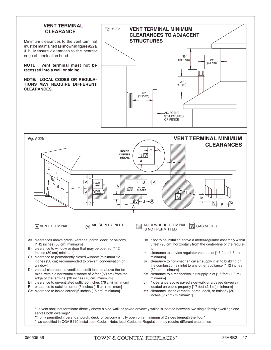
Minimum clearances to the vent terminal must be maintained as shown in figure #22a
&b. Measure clearances to the nearest edge of termination hood.
NOTE: Vent terminal must not be recessed into a wall or siding.
NOTE: LOCAL CODES OR REGULA- TIONS MAY REQUIRE DIFFERENT CLEARANCES.
Fig. # 22a | VENT TERMINAL MINIMUM |
|
| CLEARANCES TO ADJACENT |
|
| STRUCTURES |
|
| 36" | 24" |
| (91.5 cm) | |
|
| (61 cm) |
| 24" |
|
| (61 cm) |
|
| 48" |
|
| (122 cm) |
|
| ADJACENT |
|
| STRUCTURES |
|
| OR FENCE |
|
Fig. # 22b
D
E
V |
L | B |
|
F
C |
VFIXED
CLOSED
V | OPEN- |
ABLE |
![]() B
B ![]()
VENT TERMINAL MINIMUM
CLEARANCES
INSIDE ![]()
![]() G
G ![]()
CORNER V
DETAIL
A![]()
![]() H
H
V |
| B | V |
|
OPEN- | FIXED |
|
| |
| ABLE | CLOSED |
| I |
|
|
|
| |
|
|
| G | M |
V J | A | V K | A |
A |
| ||
|
|
|
V VENT TERMINAL | A AIR SUPPLY INLET |
A= clearances above grade, veranda, porch, deck, or balcony [* 12 inches (30 cm) minimum]
B= clearance to window or door that may be opened [* 12 inches (30 cm) minimum]
C= clearance to permanently closed window [minimum 12 inches (30 cm) recommended to prevent condensation on window]
D= vertical clearance to ventilated soffi t located above the ter- minal within a horizontal distance of 2 feet (60 cm) from the edge of the terminal [30 inches (76 cm) minimum]
E= clearance to unventilated soffi t [30 inches (76 cm) minimum] F= clearance to outside corner [6 inches (15 cm) minimum] G= clearance to inside corner [6 inches (15 cm) minimum]
AREA WHERE TERMINAL | G GAS METER | |
IS NOT PERMITTED |
| |
H= | * not to be installed above a meter/regulator assembly within | |
| 3 feet (90 cm) horizontally from the | |
| tor |
|
I= | clearance to service regulator vent outlet [* 6 feet (1.8 m) | |
| minimum] |
|
J= | clearance to | |
| the combustion air inlet to any other appliance [* 12 inches | |
| (30 cm) minimum] |
|
K= | clearance to a mechanical air supply inlet [* 6 feet (1.8 m) | |
| minimum] |
|
L= | ^ clearance above paved | |
| located on public property [* 7 feet (2.1 m) minimum] | |
M= | clearance under veranda, porch, deck, or balcony [30 | |
| inches (76 cm) minimum**] | |
^a vent shall not terminate directly above a
** only permitted if veranda, porch, deck, or balcony is fully open on a minimum of 2 sides beneath the fl oor*
* as specifi ed in CGA B149 Installation Codes, Note: local Codes or Regulation may require different clearances
36ARB2 17 |