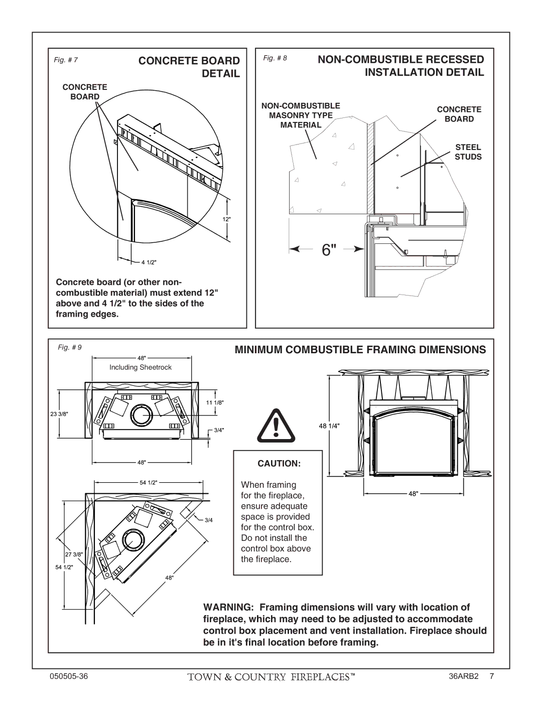
Fig. # 7 | CONCRETE BOARD |
| DETAIL |
CONCRETE
BOARD
Concrete board (or other non- combustible material) must extend 12" above and 4 1/2" to the sides of the framing edges.
Fig. # 8 NON-COMBUSTIBLE RECESSED
INSTALLATION DETAIL
CONCRETE | ||
MASONRY TYPE | ||
BOARD | ||
MATERIAL | ||
| ||
| STEEL | |
| STUDS |
6" ![]()
Fig. # 9 |
|
|
|
|
|
|
|
|
|
|
|
|
|
|
|
|
|
| MINIMUM COMBUSTIBLE FRAMING DIMENSIONS | ||||||||||
|
|
|
|
|
|
|
|
|
|
|
|
|
|
|
|
|
|
|
|
|
|
|
|
| |||||
|
|
|
|
|
|
| Including Sheetrock |
|
|
|
|
|
|
|
|
|
|
| |||||||||||
|
|
|
|
|
|
|
|
|
|
|
|
|
|
|
|
|
|
|
|
|
|
|
|
|
|
|
|
|
|
|
|
|
|
|
|
|
|
|
|
|
|
|
|
|
|
|
|
|
|
|
|
|
|
|
|
|
|
|
|
|
|
|
|
|
|
|
|
|
|
|
|
|
|
|
|
|
|
|
|
|
|
|
|
|
|
|
|
|
|
|
|
|
|
|
|
|
|
|
|
|
|
|
|
|
|
|
|
|
|
|
|
|
|
|
|
|
|
|
|
|
|
|
|
|
|
|
|
|
|
|
|
|
|
|
|
|
|
|
|
|
|
|
|
|
|
|
|
|
|
|
|
|
|
|
|
|
|
|
|
|
|
|
|
|
|
|
|
|
|
|
|
|
|
|
|
|
|
|
|
|
|
|
|
|
|
|
|
|
|
|
|
|
|
|
|
|
|
|
|
|
|
|
|
|
|
|
|
|
|
|
|
|
|
|
|
|
|
|
|
|
|
|
|
|
|
|
|
|
|
|
|
|
|
|
|
|
|
|
|
|
|
|
|
|
|
|
|
|
|
|
|
|
|
|
|
|
|
|
|
|
|
|
|
|
|
|
|
|
|
|
|
|
|
|
|
|
|
|
|
|
|
|
|
|
|
|
|
|
|
|
|
|
|
|
|
|
|
|
|
|
|
|
|
|
|
|
|
|
|
|
|
|
|
|
|
|
|
|
|
|
|
|
|
|
|
|
|
|
|
|
|
|
|
|
|
|
|
|
|
|
|
|
|
|
|
|
|
|
|
|
|
|
|
|
|
|
|
|
|
|
|
|
|
|
|
|
|
|
|
|
|
|
|
|
|
|
|
|
|
|
|
|
|
|
|
|
|
|
|
CAUTION:
When framing for the fi replace, ensure adequate space is provided for the control box. Do not install the control box above the fi replace.
WARNING: Framing dimensions will vary with location of fireplace, which may need to be adjusted to accommodate control box placement and vent installation. Fireplace should be in it's final location before framing.
36ARB2 7 |