GAS SUPPLY
Caution: The gas line should be installed by a qualified service person in accordance with all building codes. This section is intended as a guide for qualified technicians installing this appliance. Consult local and/or national building codes before proceeding.
A gas supply line access hole is located at the bottom right side of the Control Box. Gas valve inlet accepts a 3/8" N.P.T. fi tting. Correct gas line diameter must be used to assure proper operation.
The gas control is equipped with a capture screw type pres- sure test port, therefore it is not necessary to provide an 1/8 inch N.P.T. plugged tapping pressure port for checking gas pressure immediately upstream of the gas supply connection to the appliance.
Correct gas pressure requirement:
| Natural Gas | Propane |
Min. Pressure | 5.0" wc | 12.5" wc |
(For purpose of input adjustment) |
|
|
Max. Pressure | 13.9" wc | 13.9" wc |
Manifold Pressure |
|
|
Maximum | 3.8" wc | 11" wc |
Minimum | 2.1" wc | 5.5" wc |
Recommended Thermostat Wire Size
Wire Size | Max. Length |
14 ga | 100 ft. |
16 ga | 60 ft. |
18 ga | 40 ft. |
20 ga | 25 ft. |
22 ga | 18 ft. |
OPTIONAL WALL SWITCH
OR THERMOSTAT (Canada Only)
Note: Use of a wall thermostat is only permitted in Canada.
WARNING: Do not connect 110 - 120 VAC to the gas control valve or control wiring system of this unit.
Manual Millivolt Valve Only: No electrical connection is re- quired for the gas system operation. The
The installation of a wall switch allows for manual remote operation of fi replace, and automatic operation with a wall thermostat. Use a switch or thermostat that is millivolt rated.
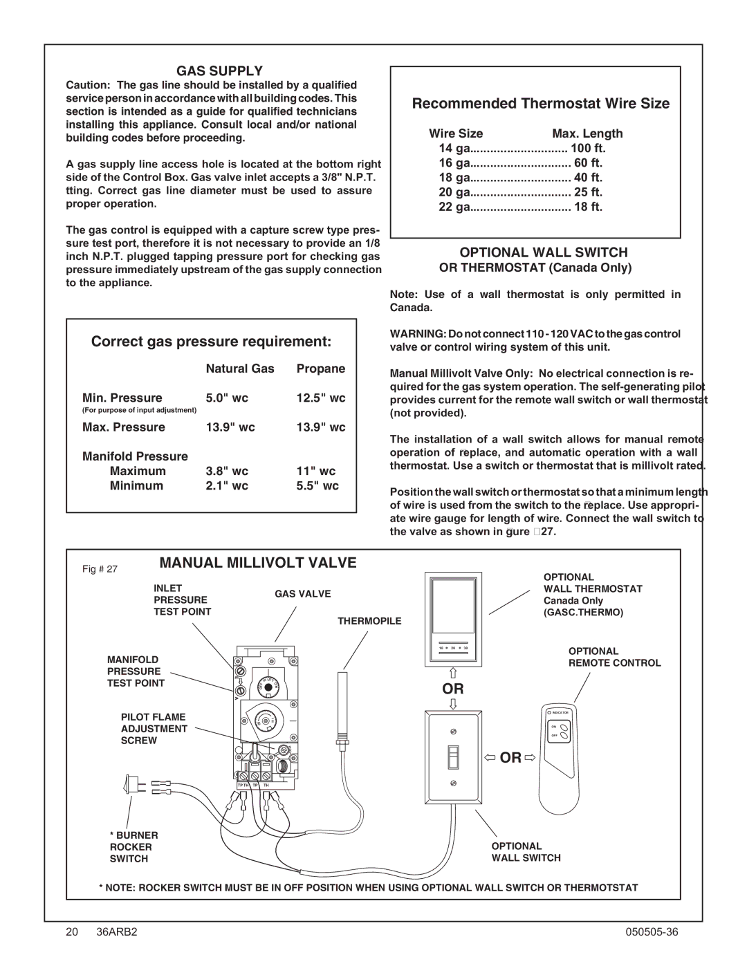
Position the wall switch or thermostat so that a minimum length of wire is used from the switch to the fi replace. Use appropri- ate wire gauge for length of wire. Connect the wall switch to the valve as shown in fi gure #27.
Fig # 27 | MANUAL MILLIVOLT VALVE | |
|
| |
| INLET | GAS VALVE |
| PRESSURE | |
|
| |
| TEST POINT | THERMOPILE |
|
| |
OPTIONAL
WALL THERMOSTAT Canada Only (GASC.THERMO)
MANIFOLD
PRESSURE
TEST POINT | E | PI LOT | |
FF | |||
O | |||
N | |||
O | |||
| A |
|
10 20 30
OR
OPTIONAL REMOTE CONTROL
PILOT FLAME |
| I |
L | H | |
ADJUSTMENT | O |
|
|
| |
SCREW |
| P |
|
| I |
|
| L |
|
| O |
|
| T |
| TP TH TP | TH |
*BURNER ROCKER SWITCH
INDICATOR
ON
OFF
OR
OPTIONAL WALL SWITCH
* NOTE: ROCKER SWITCH MUST BE IN OFF POSITION WHEN USING OPTIONAL WALL SWITCH OR THERMOTSTAT
20 36ARB2 |