4.3 Rear panel
EN
|
|
|
|
|
|
|
|
|
|
|
|
|
|
|
|
|
|
|
|
|
|
|
|
|
|
|
|
|
|
|
|
|
|
|
|
|
|
|
|
|
|
|
|
|
|
|
|
|
|
|
|
|
|
|
|
|
|
|
|
|
|
|
|
|
|
|
|
|
|
|
|
|
|
|
|
|
|
|
|
|
|
|
|
|
|
|
|
|
|
|
|
|
|
|
|
|
|
|
|
|
|
|
|
|
|
|
|
|
|
|
|
|
|
|
|
|
|
|
|
|
|
|
|
|
|
|
|
|
|
|
|
|
|
|
|
|
|
|
|
|
|
|
|
|
|
|
|
|
|
|
|
|
|
|
|
|
|
|
|
|
|
|
|
|
|
|
|
|
|
|
|
|
|
|
|
|
|
|
|
|
|
|
|
|
|
|
|
|
|
|
|
|
|
|
|
|
|
|
|
|
|
|
|
|
|
|
|
|
|
|
|
|
|
|
|
|
|
|
|
|
|
|
|
|
|
|
|
|
|
|
|
|
|
|
|
|
|
|
|
|
|
|
|
|
|
|
|
|
|
|
|
|
|
|
|
|
|
|
|
|
|
|
|
|
|
|
|
|
|
|
|
|
|
|
|
|
|
|
|
|
|
|
|
|
|
|
|
|
|
|
|
|
|
|
|
|
|
|
|
| Q W | E R | T Y U I O | P | P | |||||||||||||||||||
|
|
|
|
|
|
|
|
|
|
|
|
|
|
|
|
|
| 10 |
| 11 |
|
| ||
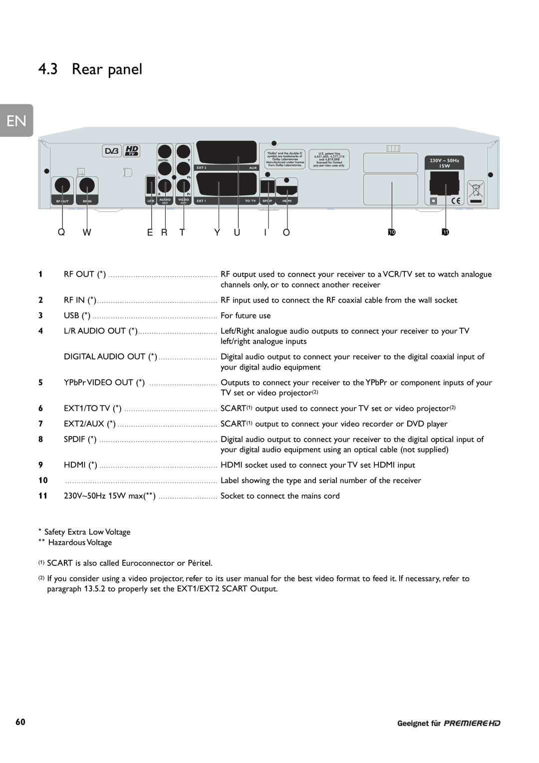
1 |
| RF OUT (*) | . . . . . . | . . . . . . | . . | . . . . . . . . . . . . . . . | RF output used to connect your receiver to a VCR/TV set to watch analogue | |||||||||||||||||
|
|
|
|
|
|
|
|
|
|
|
| channels only, or to connect another receiver |
|
|
|
|
|
|
| |||||
2 |
| RF IN (*) | . . . . . . | . . . . . . | . . | . . . . . . . . . . . . . . . | RF input used to connect the RF coaxial cable from the wall socket | |||||||||||||||||
3 |
| USB (*) | . . . . . . | . . . . . . | . . | . . . . . . . . . . . . . . . | For future use |
|
|
|
|
|
|
| ||||||||||
4 |
| L/R AUDIO OUT (*). . . . | . . | . . . . . . | . . . . . . | . . | . . . . . . . . . . . . . . . | Left/Right analogue audio outputs to connect your receiver to your TV | ||||||||||||||||
|
|
|
|
|
|
|
|
|
|
|
| left/right analogue inputs |
|
|
|
|
|
|
| |||||
DIGITAL AUDIO OUT (*) . . . . . . . . . . . . . . . . . . . . . . . . . . Digital audio output to connect your receiver to the digital coaxial input of
your digital audio equipment
5 | YPbPr VIDEO OUT (*) | Outputs to connect your receiver to the YPbPr or component inputs of your | |
|
| TV set or video projector(2) | |
6 | EXT1/TO TV (*) | SCART(1) | output used to connect your TV set or video projector(2) |
7 | EXT2/AUX (*) | SCART(1) | output to connect your video recorder or DVD player |
8 | SPDIF (*) | Digital audio output to connect your receiver to the digital optical input of | |
|
| your digital audio equipment using an optical cable (not supplied) | |
9 | HDMI (*) | HDMI socket used to connect your TV set HDMI input | |
10 | . . . . . . . . . . . . . . . . . . . . . . . . . . . . . . . . . . . . . . . . . . . . . . . . . . . . . . . . . . . . . . . . . . . | Label showing the type and serial number of the receiver | |
11 | 230V~50Hz 15W max(**) | Socket to connect the mains cord | |
*Safety Extra Low Voltage ** Hazardous Voltage
(1)SCART is also called Euroconnector or Péritel.
(2)If you consider using a video projector, refer to its user manual for the best video format to feed it. If necessary, refer to paragraph 13.5.2 to properly set the EXT1/EXT2 SCART Output.
60