21 | ENGLISH |
|
|
´SET ADDRESS
This function allows to assign an unique address to each monitor in a Daisy Chain connection. This local operation is executed once during instal- lation. The address can be in the range
Note: Care must be taken to assign different addresses to each of the monitors connected in one Chain.
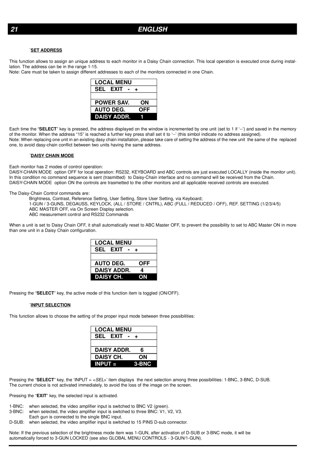
LOCAL MENU
SEL EXIT - +
POWER SAV. ON
AUTO DEG. OFF
DAISY ADDR. 1
Each time the “SELECT” key is pressed, the address displayed on the window is incremented by one unit (set to 1 if
Note: When replacing one unit in an existing dasy chain installation, please take care of setting the address of the new unit the same of the replaced one, to avoid
´DAISY CHAIN MODE
Each monitor has 2 modes of control operation:
The
Brightness, Contrast, Reference Setting, User Setting, Store User Setting, via Keyboard;
ABC measurement control and RS232 Commands
When a unit is set to Daisy Chain OFF, it shall automatically reset to ABC Master OFF, to prevent the possibility to set to ABC Master ON in more than one unit in a Daisy Chain configuration.
LOCAL MENU
SEL EXIT - +
|
| |
AUTO DEG. | OFF | |
DAISY ADDR. | 4 | |
DAISY CH. | ON | |
Pressing the “SELECT” key, the active mode of this function item is toggled (ON/OFF).
´INPUT SELECTION
This function allows to choose the setting of the proper input mode between three possibilities:
LOCAL MENU
| SEL EXIT - | + |
|
|
|
|
|
| DAISY ADDR. | 6 |
|
| DAISY CH. | ON |
|
| INPUT = |
|
|
Pressing the “SELECT” key, the ‘INPUT = <SEL>’ item displays the next selection among three possibilities:
Pressing the “EXIT” key, the selected input is activated.
Note: If the previous selection of the brightness mode item was