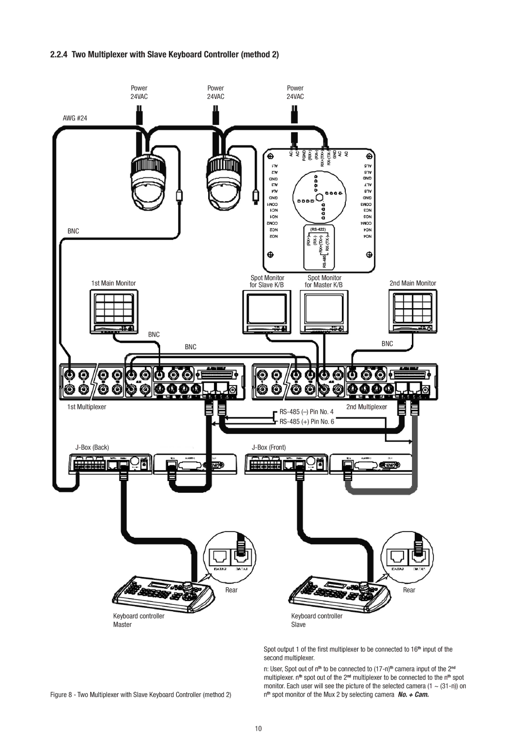
2.2.4 Two Multiplexer with Slave Keyboard Controller (method 2)
Power | Power | Power |
24VAC | 24VAC | 24VAC |
AWG #24
BNC
1st Main Monitor | Spot Monitor | Spot Monitor |
for Slave K/B | for Master K/B |
BNC
BNC
1st Multiplexer | ||
| ||
| (+) Pin No. 6 | |
|
| Rear |
Keyboard controller | Keyboard controller |
Master | Slave |
2nd Main Monitor
BNC
2nd Multiplexer
Rear
Figure 8 - Two Multiplexer with Slave Keyboard Controller (method 2)
Spot output 1 of the first multiplexer to be connected to 16th input of the second multiplexer.
n:User, Spot out of nth to be connected to
10
