Gripper Operation and Programming
4.3 Gripper I/O
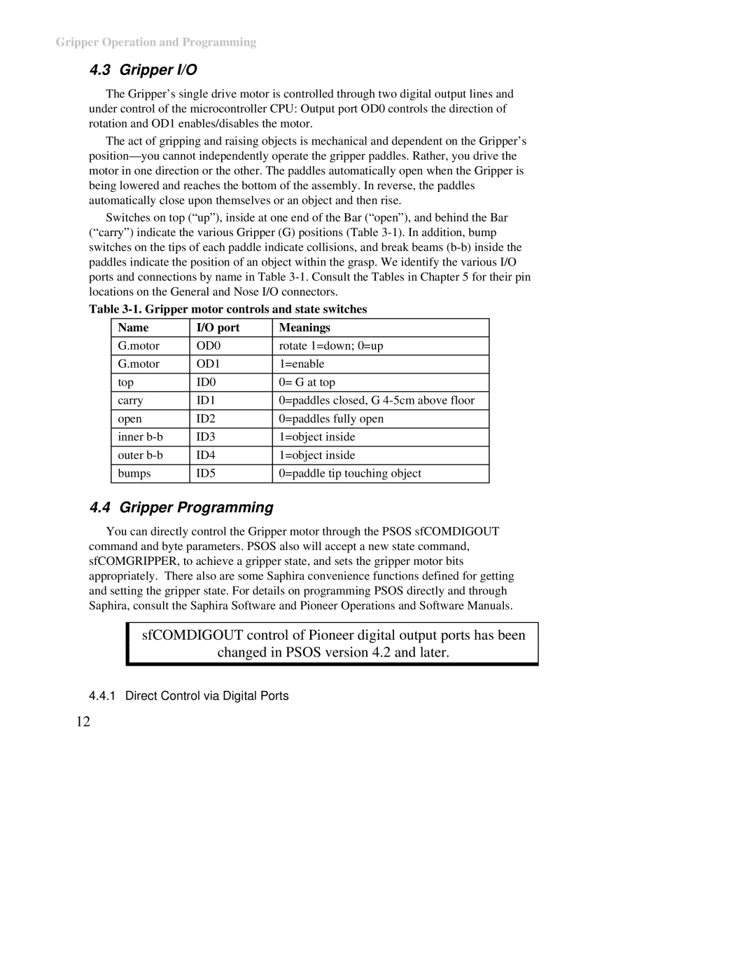
The Gripper’s single drive motor is controlled through two digital output lines and under control of the microcontroller CPU: Output port OD0 controls the direction of rotation and OD1 enables/disables the motor.
The act of gripping and raising objects is mechanical and dependent on the Gripper’s
Switches on top (“up”), inside at one end of the Bar (“open”), and behind the Bar (“carry”) indicate the various Gripper (G) positions (Table
Table
Name | I/O port | Meanings |
|
|
|
G.motor | OD0 | rotate 1=down; 0=up |
|
|
|
G.motor | OD1 | 1=enable |
|
|
|
top | ID0 | 0= G at top |
|
|
|
carry | ID1 | 0=paddles closed, G |
|
|
|
open | ID2 | 0=paddles fully open |
|
|
|
inner | ID3 | 1=object inside |
|
|
|
outer | ID4 | 1=object inside |
|
|
|
bumps | ID5 | 0=paddle tip touching object |
|
|
|
4.4 Gripper Programming
You can directly control the Gripper motor through the PSOS sfCOMDIGOUT command and byte parameters. PSOS also will accept a new state command, sfCOMGRIPPER, to achieve a gripper state, and sets the gripper motor bits appropriately. There also are some Saphira convenience functions defined for getting and setting the gripper state. For details on programming PSOS directly and through Saphira, consult the Saphira Software and Pioneer Operations and Software Manuals.
sfCOMDIGOUT control of Pioneer digital output ports has been
changed in PSOS version 4.2 and later.
4.4.1 Direct Control via Digital Ports
12
