Experimenter’s Module
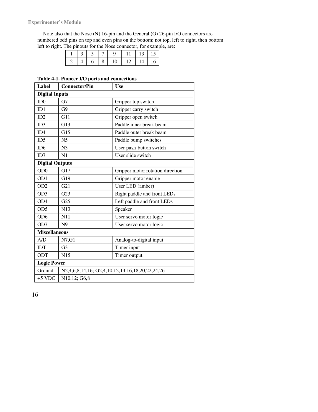
Note also that the Nose (N)
|
| 1 | 3 |
| 5 | 7 | 9 |
| 11 |
| 13 | 15 |
| |
|
|
|
|
|
|
|
|
|
|
|
|
|
|
|
|
| 2 | 4 |
| 6 | 8 | 10 |
| 12 |
| 14 | 16 |
| |
|
|
|
|
|
|
|
|
|
|
|
|
| ||
Table |
|
|
| |||||||||||
|
|
|
|
|
|
|
|
|
| |||||
Label | Connector/Pin |
|
| Use |
|
|
|
|
| |||||
|
|
|
|
|
|
|
|
|
|
|
|
|
| |
Digital Inputs |
|
|
|
|
|
|
|
|
|
|
|
| ||
|
|
|
|
|
|
|
| |||||||
ID0 | G7 |
|
|
|
|
| Gripper top switch | |||||||
|
|
|
|
|
|
|
| |||||||
ID1 | G9 |
|
|
|
|
| Gripper carry switch | |||||||
|
|
|
|
|
|
|
| |||||||
ID2 | G11 |
|
|
|
|
| Gripper open switch | |||||||
|
|
|
|
|
|
|
| |||||||
ID3 | G13 |
|
|
|
|
| Paddle inner break beam | |||||||
|
|
|
|
|
|
|
| |||||||
ID4 | G15 |
|
|
|
|
| Paddle outer break beam | |||||||
|
|
|
|
|
|
|
| |||||||
ID5 | N5 |
|
|
|
|
| Paddle bump switches | |||||||
|
|
|
|
|
|
|
| |||||||
ID6 | N3 |
|
|
|
|
| User | |||||||
|
|
|
|
|
|
|
| |||||||
ID7 | N1 |
|
|
|
|
| User slide switch | |||||||
|
|
|
|
|
|
|
|
|
|
|
|
|
| |
Digital Outputs |
|
|
|
|
|
|
|
|
|
|
|
| ||
|
|
|
|
|
|
|
| |||||||
OD0 | G17 |
|
|
|
|
| Gripper motor rotation direction | |||||||
|
|
|
|
|
|
|
| |||||||
OD1 | G19 |
|
|
|
|
| Gripper motor enable | |||||||
|
|
|
|
|
|
|
| |||||||
OD2 | G21 |
|
|
|
|
| User LED (amber) | |||||||
|
|
|
|
|
|
|
| |||||||
OD3 | G23 |
|
|
|
|
| Right paddle and front LEDs | |||||||
|
|
|
|
|
|
|
| |||||||
OD4 | G25 |
|
|
|
|
| Left paddle and front LEDs | |||||||
|
|
|
|
|
|
|
|
|
|
| ||||
OD5 | N13 |
|
|
|
|
| Speaker |
|
|
| ||||
|
|
|
|
|
|
|
| |||||||
OD6 | N11 |
|
|
|
|
| User servo motor logic | |||||||
|
|
|
|
|
|
|
| |||||||
OD7 | N9 |
|
|
|
|
| User servo motor logic | |||||||
|
|
|
|
|
|
|
|
|
|
|
|
|
| |
Miscellaneous |
|
|
|
|
|
|
|
|
|
|
|
| ||
|
|
|
|
|
|
|
| |||||||
A/D | N7,G1 |
|
|
|
|
| ||||||||
|
|
|
|
|
|
|
|
|
| |||||
IDT | G3 |
|
|
|
|
| Timer input |
|
| |||||
|
|
|
|
|
|
|
|
|
| |||||
ODT | N15 |
|
|
|
|
| Timer output |
|
| |||||
|
|
|
|
|
|
|
|
|
|
|
|
|
| |
Logic Power |
|
|
|
|
|
|
|
|
|
|
|
| ||
|
| |||||||||||||
Ground | N2,4,6,8,14,16; G2,4,10,12,14,16,18,20,22,24,26 | |||||||||||||
|
|
|
|
|
|
|
|
|
|
|
| |||
+5 VDC | N10,12; G6,8 |
|
|
|
|
|
|
|
|
|
| |||
|
|
|
|
|
|
|
|
|
|
|
|
|
|
|
16