Overview
In transition from the fully down/open position to their up/closed state, the Gripper paddles close together horizontally until they pinch an object or close on themselves. At that point, the entire Bar and Gripper Assembly rises up
The reverse cycle lowers the Gripper Bar and paddles to the bottom of the assembly, whereupon the paddles separate, dropping any contents, and open to their fully down/open position.
Two “bump”
Three other switches sense the Gripper’s paddle positions. One switch inside the Bar is on when the Gripper paddles are in their fully open position. Another at the top of the Bar toggles on when the Gripper reaches its fully up position. A third “carry” switch, located behind the Bar, indicates when the Gripper is between 1.5 and 2 inches
2.3.2 Experimenter’s Module Description
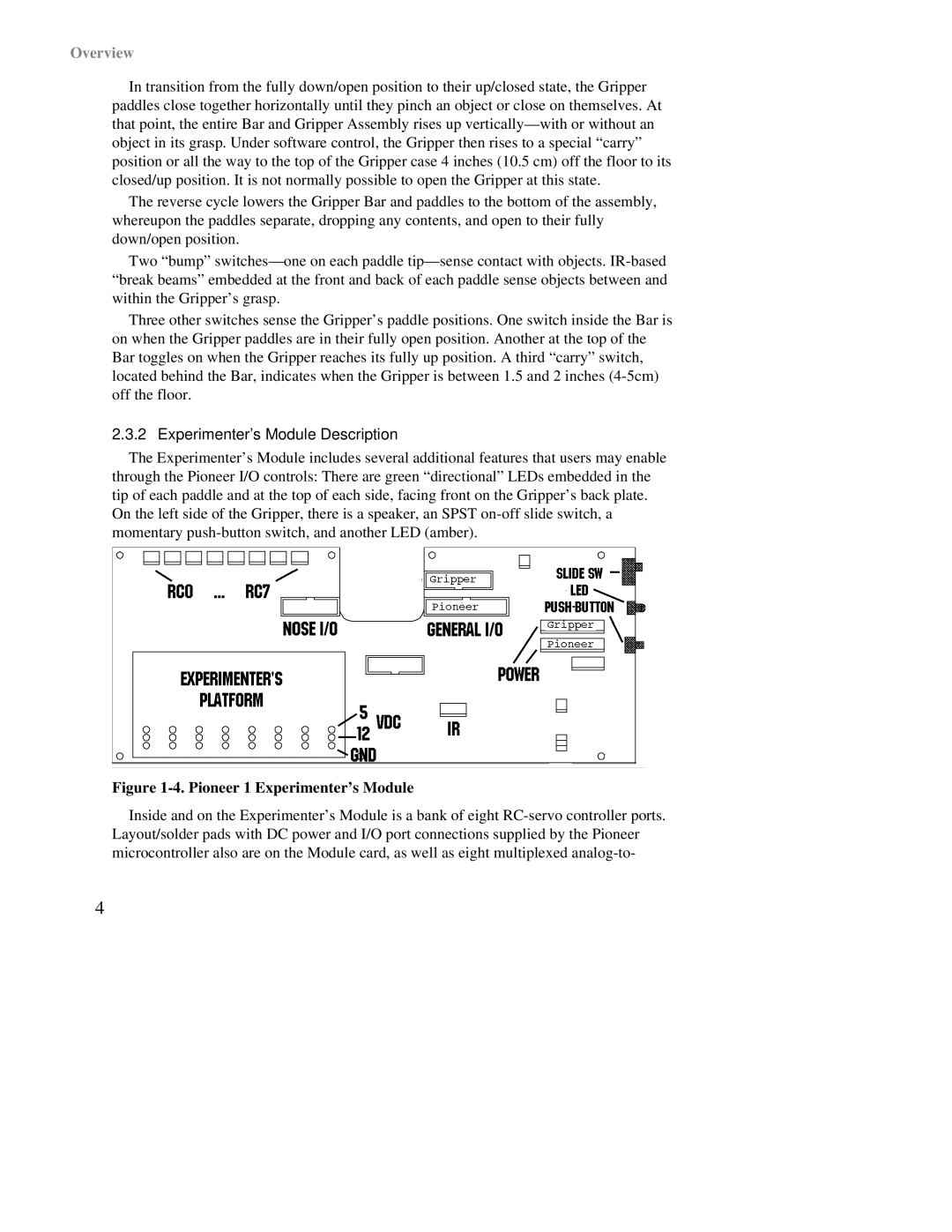
The Experimenter’s Module includes several additional features that users may enable through the Pioneer I/O controls: There are green “directional” LEDs embedded in the tip of each paddle and at the top of each side, facing front on the Gripper’s back plate. On the left side of the Gripper, there is a speaker, an SPST
Figure 1-4. Pioneer 1 Experimenter’s Module
Inside and on the Experimenter’s Module is a bank of eight
4