Per 1000Base-T port
LED | Color | Function | |
LNK/ACT | Green | Lit: indicate the link through that port is successfully established. | |
Blink: indicate that the switch is actively sending or receiving data over that port. | |||
|
| ||
|
|
| |
SPEED | Green/orange | Green: indicate that the port is operating at 1000Mbps. | |
|
| Orange: indicate that the port is operating at 100Mbps. |
Per SFP-Mini-GBIC port
LED | Color | Function |
|
|
|
LNK/ACT | Green | Lit: indicate the link through that port is successfully established. | |
Blink: indicate that the switch is actively sending or receiving data over that port. | |||
|
|
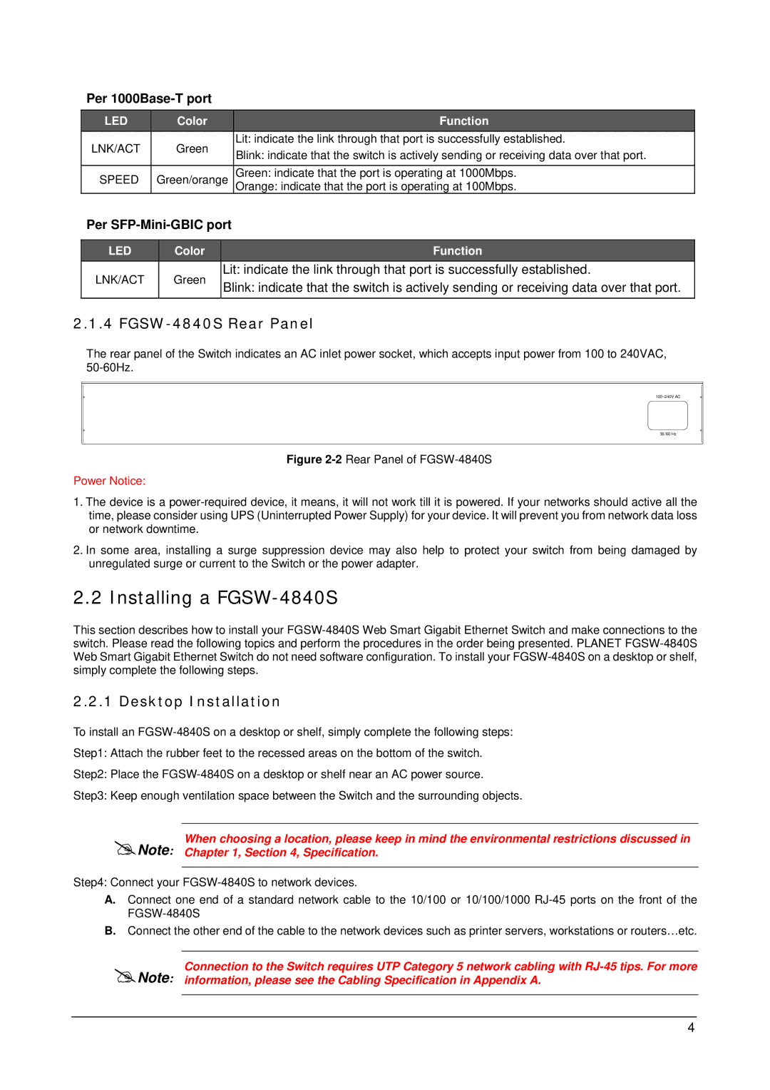
2.1.4 FGSW-4840S Rear Panel
The rear panel of the Switch indicates an AC inlet power socket, which accepts input power from 100 to 240VAC,
100~240V AC
50/60 Hz
Figure 2-2 Rear Panel of FGSW-4840S
Power Notice:
1.The device is a
2.In some area, installing a surge suppression device may also help to protect your switch from being damaged by unregulated surge or current to the Switch or the power adapter.
2.2 Installing a FGSW-4840S
This section describes how to install your
2.2.1 Desktop Installation
To install an
Step1: Attach the rubber feet to the recessed areas on the bottom of the switch.
Step2: Place the
Step3: Keep enough ventilation space between the Switch and the surrounding objects.
When choosing a location, please keep in mind the environmental restrictions discussed in Note: Chapter 1, Section 4, Specification.
Step4: Connect your
A.Connect one end of a standard network cable to the 10/100 or 10/100/1000
B.Connect the other end of the cable to the network devices such as printer servers, workstations or routers…etc.
Connection to the Switch requires UTP Category 5 network cabling with
Note: information, please see the Cabling Specification in Appendix A.
4
