Vortex EF2241 Reference Manual
Page
Introduction
INTRODUCTION
Welcome How to Use This Manual
PRODUCT FEATURES
Product Registration
Product
Inputs and Outputs Remote Control
Tools Needed for Installation
PRE-INSTALLATION
What’s Included
What’s Not Included
EF2241 FRONT AND REAR PANELS
10. INPUT PARALLEL PORT. Parallel logic input
CONNECTING THE EF2241 TO OTHER EQUIPMENT
INSTALLATION
Recommendation For Easy Access
Instructions for Securing Power Supply to Back of EF2241
Typical EF2241 Connections
CONNECTING MULTIPLE VORTEX DEVICES
DEVICE IDS ON THE EF BUS
Note. The EF Bus must be connected so that the EF Bus In of one
Terminating the EF2241
FACTORY DEFAULT SETTINGS PRESET
Preset
INSTALLATION
VORTEX EF2241 Reference Manual
Technical Support
Presets and Multiple Vortex Devices
Pick a Standard Signal Level
CHECK SURROUNDING EQUIPMENT
Configure Program Audio Sources
Configure the matrix mixer input from the codec output. The input
Select Phantom Power for Inputs
INPUT SETTINGS
INTEGRATING THE EF2241 INTO YOUR SYSTEM
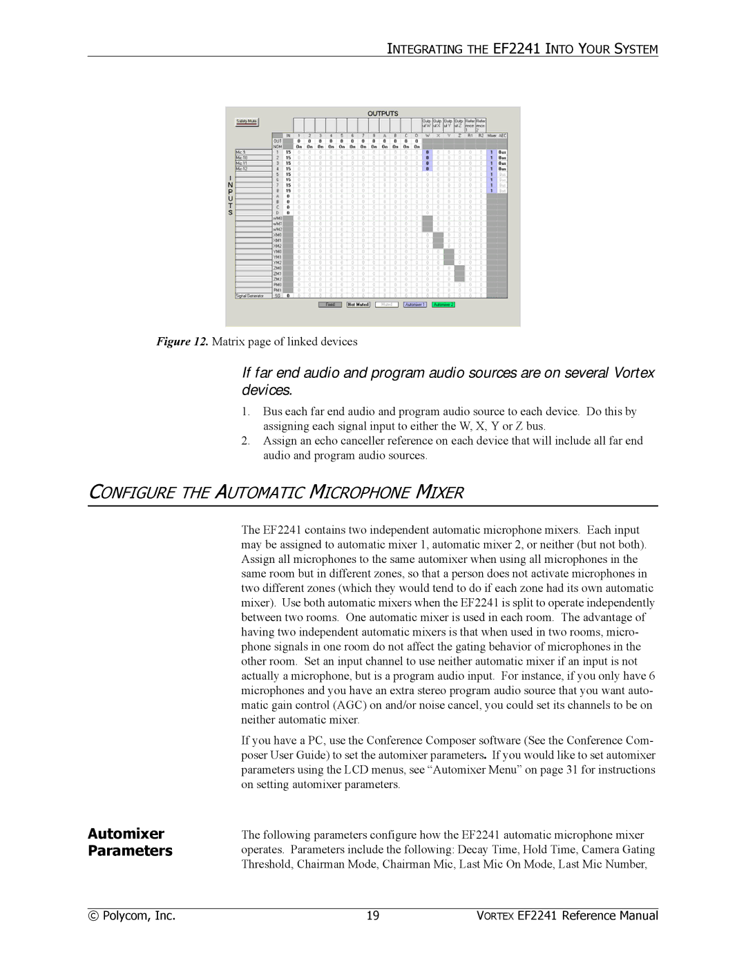
CALIBRATION
ADJUST THE INPUT GAIN IN THIS WAY
Set Levels on Line Input Channels
IF THE AGC METER SHOWS
BUILD YOUR ECHO CANCELLER REFERENCE
SET UP THE PHONE INTERFACE
ECHO CANCELLER REFERENCE FOR MULTIPLE VORTEX DEVICES
Customize Setting for Your Particular Application
Bus Reference
Setting up the
Vortex device
If all far end audio and program audio sources are on the same
Automixer Parameters
CONFIGURE THE AUTOMATIC MICROPHONE MIXER
Mixer Settings
Global Settings
Channel Settings
AUTOMIXER SETTINGS FOR MULTIPLE VORTEX DEVICES
Automixer and Bus Mixer Settings Operating as an Independent
CONFIGURE THE MATRIX MIXER
Default Settings
BUILDING YOUR SYSTEM WITH MULTIPLE VORTEX DEVICES
1. Assign Inputs 2. Assign Outputs
3. Configure the submatrix
THE EF BUS
THE EF BUS
OTHER EF2241 FEATURES
PRESETS
4. Configure Your Echo Canceller Reference
THE EF BUS
LCD Menu Tree
LCD MENU STRUCTURE
must be flashing. To make the parameter flash assuming the front panel is not locked press ENTER. Once the parameter is flashing, use the UP and DOWN buttons to adjust the parameter value. The parameter is instantly updated while it is being adjusted - you should hear changes as the parameter is changing. RS-232 control strings are also sent via the RS-232 port so your remote control device is instanta- neously updated as well. Press ENTER to select and store the parameter value or press ESC to cancel the selected value and return to the old value. Pressing HOME has the effect of pressing ESC then HOME, so the selected value will be cancelled and the menu will return to the top of the menu tree
Figure 17. EF2241
SYSTEM MENU
PHONE CONTROL
Automatic Gain Control Inputs 1-4, T. This enables automatic gain con
INPUTS
Figure 19. EF2241
AUTOMIXER MENU
OUTPUTS
Global Settings Mixer Settings Channel Settings
Outputs
Global Settings
Global Settings
Automixer
Decay Hold Time Camera Gating Threshold
Channel Settings
Mixer Settings
Mixer Settings AM1/AM2 Bus ID Chairman Mode Chairman Mic
Last Mic On Mode Last Mic Number Local Max NOM Global Max NOM
Matrix
MATRIX MENU
Main Matrix
SubMatrix
Input/Output EQ Channel Band
PARAMETRIC EQ MENU
PRESETS
MACROS
Presets
Figure 25. EF2241
AUTOMATIC MICROPHONE MIXER
TROUBLESHOOTING
No microphones are gating Some microphones are not gating
Too many microphones are gating
MATRIX MIXER
ECHO CANCELLER REFERENCE
RESIDUAL ECHO
Room Audio Sounds Choppy
Finding the Source of Echo Room Gain
Figure 28. Room Gain
Excessive Room Gain
In-Conference Quick Check Excessive Microphone Amplification
Microphone
Insufficient
Amplification
Nonlinearity
Email vortex@polycom.com
CONTACTING TECHNICAL SUPPORT
MECHANICAL SPECIFICATIONS
TECHNICAL SPECIFICATIONS
ELECTRICAL SPECIFICATIONS
PERFORMANCE SPECIFICATIONS
COMPLIANCE
USA and Canada
US Telco requirements
Canadian Telco Requirements
Automatic Dialing Telco Connector
Mains powered POT’s Voice Telephony without Emergency 000 dialing
Australia
Installation Instructions
Rest of World
This page was intentionally left blank
TECHNICAL SPECIFICATIONS
VORTEX EF2241 Reference Manual
Technical Support
Declaration of Conformity
CE Mark R& TTE Directive
Konformitetserklæring
Konformitätserklärung
Technical Support
VORTEX EF2241 Reference Manual
CONFERENCE SYSTEM DESIGN
Noise and Reverberation Consider Room Gain
Figure 29. Room Gain
EF2241 BLOCK DIAGRAM
EN Echo Canceller, Noise Canceller
V ORTEX EF2241 Reference Manual
EF Bus
CONNECTOR PINOUTS
Cat-5 Plug Pinout
RJ11 Plug Pinout
Input/Output Remote Control Port
Power Supply Input
Mic/Line Inputs, Line Inputs, Line Outputs
MAKING AN EF BUS TERMINATOR
CONNECTING UNBALANCED RCA TO BALANCED MINI PHOENIX
Instructions
1 2 3 4 5 6 7
ADDITIONAL NOTES
WARRANTY INFORMATION
What is covered For how long What we will do Limitations
What we ask you to do
What this warranty does not cover
State Law Rights
No User Serviceable Parts
DEFINITION OF TERMS
Echo Canceller
Acoustic Echo
Acoustic Gain Ambient Level Automatic Gain Control AGC
NOM NOM Attenuation NOM Bus Presets Room Gain
EF Bus Equalization Line Echo Macros Matrix Mixer Noise Cancellation
room gain of this microphone channel is said to be 0 dB. If the reflected signal picked up by the microphone is higher than the level of the signal sent to the line output to your amplifier, that microphone channel has positive room gain. The more positive the room gain, the harder the AEC must work to determine which signal is an echo and which is a local speech signal
INDEX
Mic/Line Inputs, Line Inputs, Line Outputs
Page
Page
1725-80098-001-C
Polycom, Inc Installed Voice Business Group
1720 Peachtree Street NW, Suite 220 Atlanta, GA
Phone 800 932-2774, 404