CONNECTOR PINOUTS
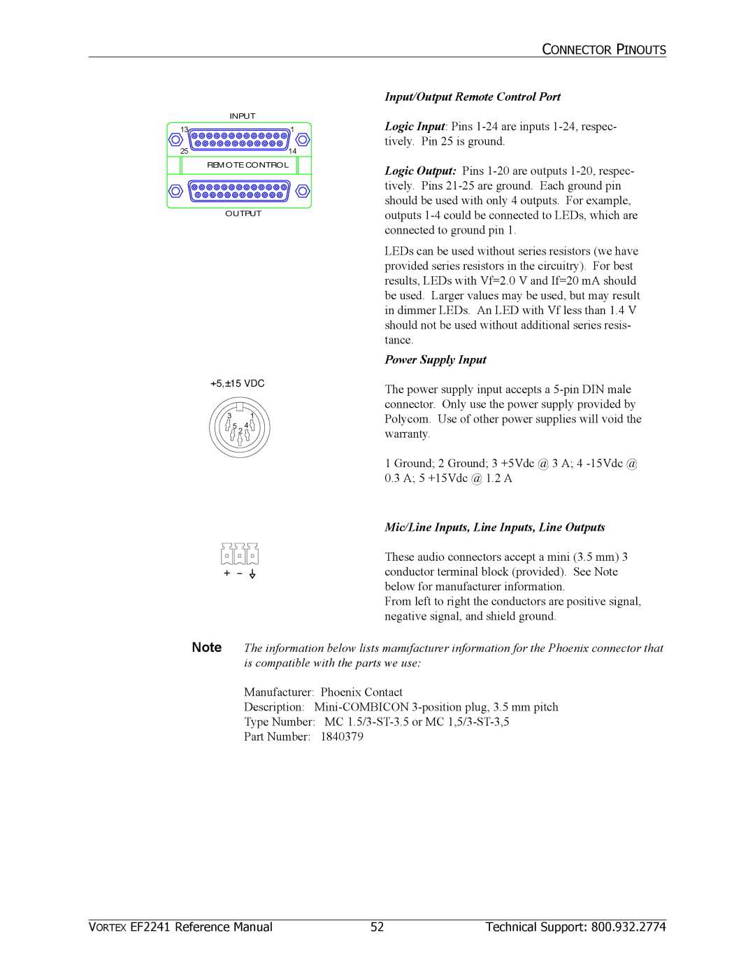
Input/Output Remote Control Port
| INPUT |
13 | 1 |
25 | 14 |
| REMOTE CONTROL |
OUTPUT
![]() 5,
5,![]() 15 VDC
15 VDC
31 ![]() 5 2 4
5 2 4 ![]()
Logic Input: Pins
Logic Output: Pins
LEDs can be used without series resistors (we have provided series resistors in the circuitry). For best results, LEDs with Vf=2.0 V and If=20 mA should be used. Larger values may be used, but may result in dimmer LEDs. An LED with Vf less than 1.4 V should not be used without additional series resis- tance.
Power Supply Input
The power supply input accepts a
1 Ground; 2 Ground; 3 +5Vdc @ 3 A; 4
Mic/Line Inputs, Line Inputs, Line Outputs
These audio connectors accept a mini (3.5 mm) 3 conductor terminal block (provided). See Note below for manufacturer information.
From left to right the conductors are positive signal, negative signal, and shield ground.
Note The information below lists manufacturer information for the Phoenix connector that is compatible with the parts we use:
Manufacturer: Phoenix Contact
Description:
Type Number: MC
Part Number: 1840379
VORTEX EF2241 Reference Manual | 52 | Technical Support: 800.932.2774 |