PRE-INSTALLATION
What’s Included
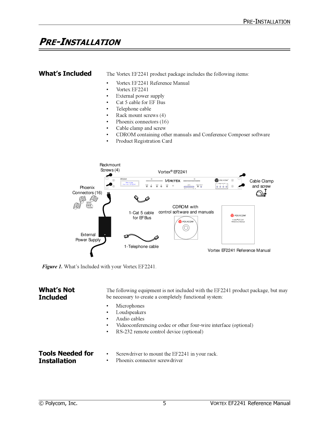
The Vortex EF2241 product package includes the following items:
•Vortex EF2241 Reference Manual
•Vortex EF2241
•External power supply
•Cat 5 cable for EF Bus
•Telephone cable
•Rack mount screws (4)
•Phoenix connectors (16)
•Cable clamp and screw
•CDROM containing other manuals and Conference Composer software
•Product Registration Card
Rackmount |
|
Screws (4) | Vortex® EF2241 |
x | x | |
x | x | |
Phoenix | ||
| ||
Connectors (16) |
|
Cable Clamp
and screw
External
Power Supply
CDROM with
Vortex® EF2241
Reference Manual
Vortex EF2241 Reference Manual
Figure 1. What’s Included with your Vortex EF2241.
What’s Not Included
The following equipment is not included with the EF2241 product package, but may be necessary to create a completely functional system:
•Microphones
•Loudspeakers
•Audio cables
•Videoconferencing codec or other
•
Tools Needed for Installation
•Screwdriver to mount the EF2241 in your rack.
•Phoenix connector screwdriver
© Polycom, Inc. | 5 | VORTEX EF2241 Reference Manual |